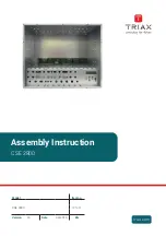
background image

  Assembly Instruction


CSE 2800

Model

Item no.

CSE 2800

325001


Version

10

Date

04/2016

EN

Summary of Contents for CSE 2800

Page 1: ...Assembly Instruction CSE 2800 Model Item no CSE 2800 325001 Version 10 Date 04 2016 EN ...

Page 2: ...e 10 4 3 Making an earth connection 11 4 4 Installing F terminals 12 4 5 Installing an additional fan 12 4 6 Mounting 13 Wall mounting 14 Upright mounting 15 Mounting inside a 19 cabinet 16 5 Installing modules 17 6 Connecting the head end station 18 6 1 Potential equalisation PE 18 6 2 Mains connection 18 6 3 LNB Power supply connections 19 6 4 RF connections 19 7 Settings 20 7 1 Contrast of the ...

Page 3: ...ation it is not admissible to mount them one upon the other without using thermic precautions e g permanently air recirculation ventilation heat deflectors etc Do not install the device in cabinets or recesses which are not ventilated If additional fans are to be used to circulate the air ensure that the system will be shut down disconnected from mains should any one of the fans fail In case of th...

Page 4: ...dules Electronic devices should never be disposed of in the household rubbish In accordance with directive 2002 96 EC of the European Parliament and the European Council from January 27 2003 which addresses old electronic and electrical devices such devices must be disposed of at a designated collection facility At the end of its service life please take your device to one of these public collecti...

Page 5: ... fulfils the guidelines and standards for CE labelling Unless otherwise noted all values are specified as typical General Slots unoccupied 8 modules 8 add on modules Permissible ambient temperature 0 C 50 C Dimensions W x H x D cm 44 3 19 x 35 5 8 HU x 22 8 Weight approx 20 kg fully equipped LNB power supply 12 V max 800 mA short circuit proof multi fused Mains unit Mains voltage 220 240V 50 60 Hz...

Page 6: ...tation is designed to supply power to components e g LNB connected upstream All RF output signals from the modules are combined via the inputs of a retro fitted active RF output collector and prepared for distribution through the RF output socket When the head end station is shipped from the factory the default setting for the control voltage for a RF output collector is maximum If necessary pleas...

Page 7: ...Locking screws incl with delivery in a separate package 2 Fastening screws 3 2 Front view without front cover 3 2 1 4 Fig 2 1 Knock outs for upgrading a RF output collector 2 Knock outs for the SAT IF input distributors 3 Control panel 4 Knock outs for F terminals ...

Page 8: ...6 4 5 3 2 1 7 Fig 4 1 Power cord socket 2 Main power switch 3 Earth connection terminal 4 SAT IF inputs 5 Knock outs for additional F terminals 6 Knock out for the optional installation of the earth connection terminal 7 RF output ...

Page 9: ...play 3 Mode indicator 4 To adjust values and functions 5 Moves the cursor adjusts functions 6 Stores the programmed data 7 To adjust values and functions 8 To switch to the next menu 9 9 pin SUB D socket for updating the operating software of the modules and the head end station 0 Moves the cursor adjusts functions ...

Page 10: ... for initial assembly Slide the front cover upwards and remove it from the head end station 4 2 Remove base plate 1 2 2 2 Fig 7 Remove the locking screw 1 Remove the fastening screws 2 If applicable unscrew the nuts of retrofitted F terminals not required for initial assembly Push the base plate in direction of the arrow and remove it ...

Page 11: ...8 1 2 Fig 8 Dismount the PE connection terminal so that it can be moved Mount the PE connection terminal according to fig 9 in position 2 as shown in fig 8 Housing Fig 9 Caution Tighten the nut until the teeth on the lock washer have penetrated the exterior coating and a good connection is made between the housing and PE connec tion terminal ...

Page 12: ... penetrated the exterior coating and a good connection is made between the housing and F terminals 4 5 Installing an additional fan If environmental conditions require the use of an additional fan one can be screwed to the inside of the base plate hole spacing 82 x 82 mm 82 mm 82 mm Fig 11 Remove base plate page 10 Mount the fan 12 V 1 A max in position 1 or 2 fig 11 to the inside of the base plat...

Page 13: ...he minimum distance requirements 500 mm above below and 75 mm behind the device at wall mounting 500 mm above and 75 mm be low behind the device at upright mounting 200 mm above below and 100 mm behind the device at mounting in a 19 cabinet will be met If mounting to a wall or on a shelf ensure that The wall or the shelf can support the weight of the head end station There is adequate air conditio...

Page 14: ... the back edge of the mounting bracket is approx 75 mm Screw in the 6 thread forming countersunk screws 2 that were supplied Attach the mounting bracket to the other side of the housing in the same way Insert wall plugs suitable for the wall properties into the wall so that they correspond to the dimensions in the following illustration fig 14 140 mm 465 mm Fig 14 Mount the head end station and sc...

Page 15: ...on the head end station housing and snap it into place The distance between the underside of the head end station and the lower edge of the mounting bracket is approx 75 mm Screw in the 6 thread forming countersunk screws 2 that were supplied Attach the mounting bracket to the other side of the housing in the same manner ...

Page 16: ...e nuts into the frame of the rack system according to the distance of the holes 5 in the mounting bracket 3 approx 190 mm Connect the head end station according to chapter 6 page 18 Put the head end station onto the support elements push it into the 19 cabinet Fasten the head end station to the prestole nuts of the 19 cabinet using the holes 5 in the mounting brackets 3 and appropriate screws To a...

Page 17: ...e housing The shorter grooves without a contact strip on the board at the rear wall of the housing are for add on modules only Open the locking device 1 in the direction of the arrow fig 17 1 Fig 17 1 2 3 Fig 18 Insert a module in grooves 1 and 2 of an open slot fig 18 and gently slide it into the head end station until it makes contact with the board on the rear wall After installing a module clo...

Page 18: ...y customer using the PE wire 6 2 Mains connection Never operate the device without a protective earth connection earth connec tion to the device and potential equalisation To maintain compliance with current EMC regulations electromagnetic com patibility it is necessary to route the power cord through the supplied ferrite sleeve Open the ferrite sleeve Make a loop in the power cord and lay the loo...

Page 19: ... current EMC regulations it is necessary to connect the lines leading in and out of the head end station using F terminals Note The F terminal at the rear panel are intended to use for RF input and RF output The following connection example shows a possible connection scheme Connect the SAT IF cables coming from the LNBs to the relevant F terminals fig 23 4 4 6 4 5 3 2 1 7 Fig 22 ...

Page 20: ...llector Setting the standard of the output signal After the output levels of the modulator modules or the modulators have been set check the master output level of the RF output collector and adjust it ac cordingly based on the requirements of the cable system Afterwards set the standard of the output signal required Setting the output level of a retrofitted RF output collector Connect the RF outp...

Page 21: ...l menu is activated SETUP Level 0 OUTPUT Using the buttons set the RF output level as required for the cable system The control voltage for a retrofittable active output collector is set Press the button The Standard of the output signal NORM menu is activated Standard of the output signal SETUP PAL BG NORM Using the buttons set the output standard as required for the cable system Always all modul...

Page 22: ...TUP S STORE MEMORY S M All programmed data is saved by pressing the button You will be re turned to the menu item Select module channel strip By pressing the button you will be returned to the menu item Select module channel strip without saving the programmed data ...

Page 23: ...anner width 11 mm 1 2 2 2 Fig 26 Position the breakthroughs in the base plate above the fastening screws 2 fig 26 Push the base plate in direction of the arrow and lock it with the locking screw 1 fig 26 Tighten the fastening screws 2 Tighten the nuts of retrofitted F terminals if applicable Hang the front cover on the fastening screws 2 page 10 fig 6 Secure the front cover using the 4 locking scr...

Page 24: ...RIAX Multimedia are registered trademarks or trademarks of the TRIAX Company or its affiliates All specifications in this guide are subject to change without further notice TRIAX A S Bjørnkærvej 3 DK 8783 Hornsyld Denmark For further information and updated manuals go to ...

Reviews: