Traxxas 4801, Assembly Manual, Tuning Manual
The Integra 4801 is a cutting-edge device that will revolutionize your daily routine. With its sleek design and advanced features, it is a must-have for tech enthusiasts. To get started quickly, we offer a free Quick Start Manual which you can download instantly from our website, making setup a breeze.
Share
Download


Reviews:
No comments
Related manuals for 4801
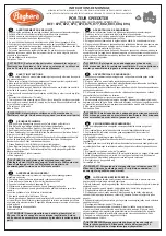
870
Brand: Baghera Pages: 3

703215410101
Brand: RUSTA Pages: 20

Kenworth W-900
Brand: REVELL Pages: 32

710
Brand: Serpent Pages: 12

Cobra GT RTR
Brand: Serpent Pages: 20

LabF101
Brand: Capricorn RC Pages: 17

A228
Brand: Ride On Cars Pages: 16

Deluxe Cars 400080
Brand: Jamara Pages: 8

460633
Brand: Jamara Pages: 16

CrossFire 150
Brand: Tomberlin Pages: 76

404980
Brand: Jamara Pages: 8

405191
Brand: Jamara Pages: 8

Power Wheels X6645
Brand: Fisher-Price Pages: 28

IGOD0534
Brand: Peg-Perego Pages: 68

KL-7012
Brand: Kalee Pages: 9

NEXX 8 T
Brand: Ofna Racing Pages: 42

Sand Rover
Brand: Tamiya Pages: 16

05 3290 EP
Brand: Jamara Pages: 20


