

7106503999 REV1.0.0
Quick Installation Guide
2.4GHz 150Mbps Outdoor Wireless Access Point
MODEL NO.
TL-WA7210N
Package Contents
TL-WA7210N
QIG
Passive PoE Injector
Power Adapter
Resource CD
Ethernet Cable
2.4GHz 150Mbps Outdoor Wireless Access Point
TL-WA7210N
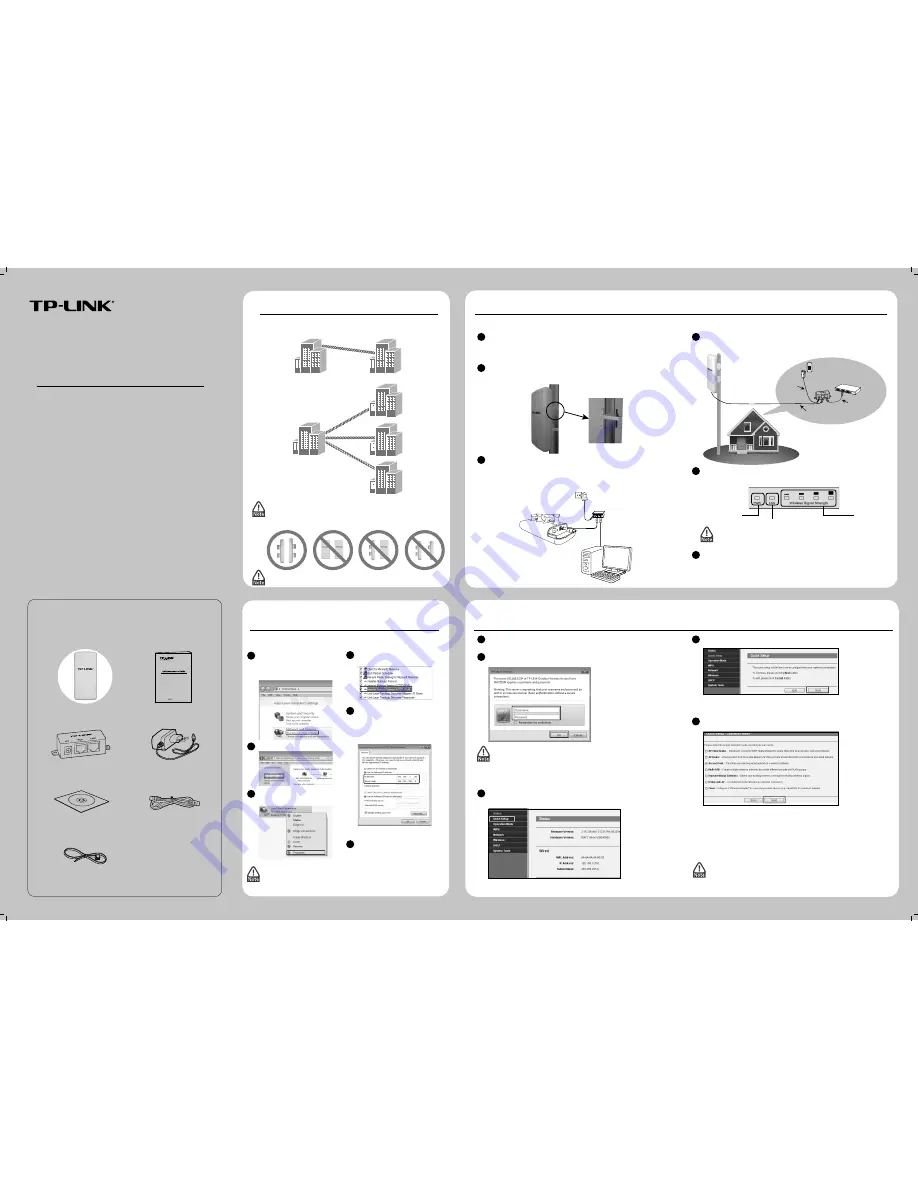
TL-WA7210N is used for remote point-to-point and point-to-multipoint
applications. It makes remote Internet share possible.
The typical connection for TL-WA7210N is shown as above. Please make
sure that the two CPEs are placed face to face, otherwise, the wireless signal
strength might be weak. The figures shown below are a few examples, and
only the first one is correct.
If you are using an external antenna to connect, please refer to Appendix 1.
Typical Network
Configuring the Device
3
1
Open your web browser, type in http://192.168.0.254 in the address field
and press Enter
.
2
A dialog box will prompt you for the User name and Password. Enter the
default values (both are admin) and click OK.
1. If the dialog box does not pop up, please refer to T3 in the Appendix 2:
Troubleshooting. Also, T2 will give you some help if you forget the
password.
2. If the device has been restored, the Welcome page will appear, please
read the TERMS OF USE carefully. Then select I agree to these terms of
use and click Login to continue.
3
The web management page will display after your successful login. Click Quick
Setup in the main menu
.
4
Then the page below will appear. Click Next
.
5
Select the Operation Mode Type according to your needs. Click Next.
a) If you want to set up a point-to-point connection with TL-WA7210N, please
skip to Configuration for Point-to-Point Connection. In this part, you will
learn about the configuration for Access Point and Client mode.
b) If you want to set the CPE to the Bridge with AP mode, please skip to
Configuration for Bridge with AP.
(To be continued...)
Configuring the Computer
2
Assign a static IP address 192.168.0.100 for your computer first before logging in
the management page. Here we take the procedures in Windows 7 for example.
1
Go to Start > Settings > Control
Panel, and then you will see the
following page. Click View
network status and tasks.
2
Click Change adapter settings.
3
Right-click Local Area Connec-
tion, then click Properties.
4
Double-click Internet Protocol
Version 4 (TCP/IPv4).
5
Select Use the following IP
address, enter 192.168.0.100 into
the IP address field and
255.255.255.0 into the Subnet
mask field
.
For configuration for other modes of TL-WA7210N, please refer to the
User Guide in the resouce CD.
Point-to-Multipoint Application
AP
Client 2
Client 3
Client 1
Point-to-Point Application
Client
AP
Connecting the Device
1
Please use only wired network connection to configure the AP.
1
2
3
Locate a suitable mounting site for your CPE. To achieve the best performance
of the devices, please select an elevated location where trees, buildings and
large steel structures will not obstruct the antenna signals and which offers
maximum line-of-sight propagation for the devices.
Adjust the direction of your CPE for a best signal. Place the straps through the
slots on the back of the CPE and then around the pole. Tighten the straps.
TL-WA7210N
Power Adapter
PoE
Computer
Connect one end of an Ethernet cable to the PoE port of the provided PoE and
the other end of the Ethernet cable to the LAN port of the CPE. Then, connect
the LAN port of the PoE to a PC using another Ethernet cable. Finally, plug the
provided power adapter into the DC jack on the PoE, and the other end to a
standard electrical wall socket.
4
The connection will be similar to the figure below after the above steps are
finished.
5
Turn on all your network devices and then check to see if the LEDs on the AP
display normally as the diagram below describes.
If the LEDs display abnormally, please check to see if all the cable
connectors (power adapter and Ethernet cable) are well connected to
your devices.
Solid light
Solid light
Solid light or flashing
OUTDOOR
INDOOR
CPE
Power Cable
Main Electrical Supply
PoE Injector
To Switch or PC
CAT5 FTP Cable Et DC Power
6
Click OK to save the configura-
tions for your computer.
6
If you use two CPEs to build the network, please make sure that the two CPEs
are placed face to face. Please refer to the Antenna Alignment to get the
optimum signal.
Mounting Kits
Please reconfigure your computer after successfully configuring the CPE.
Select Obtain an IP address automatically and Obtain DNS server
address automatically in step 5, then click OK.


