


Part No. 09173SL (Rev. A)
Service Manual
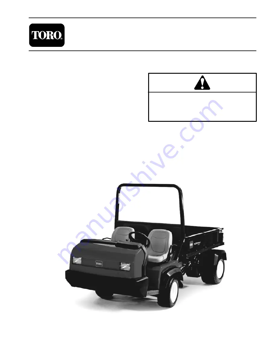
Workman
R
HD Series
Preface
The purpose of this publication is to provide the service
technician with information for troubleshooting, testing,
and repair of major systems and components on the
Workman HD, HDX and HDX--D vehicles.
REFER TO THE OPERATOR’S MANUAL FOR OPER-
ATING,
MAINTENANCE
AND
ADJUSTMENT
INSTRUCTIONS. For reference, insert a copy of the
Operator’s Manual and Parts Catalog for your machine
into Chapter 2 of this service manual. Additional copies
of the Operator’s Manual and Parts Catalog are avail-
able on the internet at www.Toro.com.
The Toro Company reserves the right to change product
specifications or this publication without notice.
This safety symbol means DANGER, WARNING,
or CAUTION, PERSONAL SAFETY INSTRUC-
TION. When you see this symbol, carefully read
the instructions that follow. Failure to obey the
instructions may result in personal injury.
NOTE:
A
NOTE
will give general information about the
correct operation, maintenance, service, testing, or re-
pair of the machine.
IMPORTANT: The IMPORTANT notice will give im-
portant instructions which must be followed to pre-
vent damage to systems or components on the
machine.
E
The Toro Company -- 2009, 2011
Summary of Contents for Workman HD Series
Page 2: ...Workman HD Series This page is intentionally blank ...
Page 4: ...Workman HD Series This page is intentionally blank ...
Page 6: ...Workman HD Series This page is intentionally blank ...
Page 46: ...Rev A Workman HDX Page 3 28 Briggs Daihatsu Gasoline Engine This page is intentionally blank ...
Page 68: ...Workman HD Page 5 4 Kohler Gasoline Engine This page is intentionally blank ...
Page 95: ...Workman HD Series Page 6 19 Drive Train This page is intentionally blank Drive Train ...
Page 140: ...Workman HD Series Page 6 64 Drive Train This page is intentionally blank ...
Page 155: ...Workman HD Series Page 7 15 Chassis This page is intentionally blank Chassis ...
Page 159: ...Workman HD Series Page 7 19 Chassis This page is intentionally blank Chassis ...
Page 167: ...Workman HD Series Page 7 27 Chassis This page is intentionally blank Chassis ...
Page 216: ...Workman HD Series Page 9 2 Hydraulic System This page is intentionally blank ...
Page 244: ...Workman HD Series Page 9 30 Hydraulic System This page is intentionally blank ...
Page 274: ...Workman HD Series Page 9 60 Hydraulic System This page is intentionally blank ...
Page 296: ...Rev A Workman HDX HDX D Page 10 22 Front Wheel Drive 4WD This page is intentionally blank ...
Page 298: ...Workman HD Series Electrical Drawings Page 11 2 This page is intentionally blank ...
Page 309: ...Page 11 13 This page is intentionally blank ...
Page 310: ...Page 11 14 Front Wire Harness Drawing Workman HD Series All Models 3RD HIGH LOCKOUT SWITCH ...
Page 318: ......


