Thales Liberty PRC7332, User Manual
The Thales Liberty PRC7332 offers unparalleled communication capabilities. Harness its full potential with our comprehensive User Manual, available for free download at manualshive.com. This manual equips you with essential instructions, ensuring seamless operation and maximizing your experience with this exceptional product. Get started today!
Share
Download


Reviews:
No comments
Related manuals for Liberty PRC7332

TRX-05W1
Brand: TRX Pages: 28

TC-780
Brand: Hytera Pages: 47

GM-1525-AM
Brand: G+M Elektronik Pages: 23

10037496
Brand: auna Pages: 152

TRAFFIC ADVISOR
Brand: Pocket Radar Pages: 2

Eversden
Brand: MAJORITY Pages: 31

DT-180
Brand: Sangean Pages: 1

DT-120CL
Brand: Sangean Pages: 1

VX-4100 Series
Brand: Vertex Standard Pages: 6

VX-4107
Brand: Vertex Standard Pages: 10

VX-4100 Series
Brand: Vertex Standard Pages: 20

VX-4000 Series
Brand: Vertex Standard Pages: 31

VX-1400
Brand: Vertex Standard Pages: 66

CR-M10DAB
Brand: JVCKENWOOD Pages: 18

VX-4200 Series
Brand: Vertex Standard Pages: 44

cNODE MiniS 1.11-50V Ti
Brand: Kongsberg Pages: 48
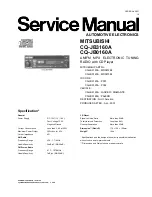
CQ-JB0160A
Brand: Mitsubishi Electric Pages: 31

TOUGHBOX
Brand: Sangean Pages: 12


