Kongsberg cNODE MiniS 1.11-50V Ti, Instruction Manual
The Kongsberg cNODE MiniS 1.11-50V Ti product comes with a comprehensive Instruction Manual that ensures easy setup and optimal usage. This manual is available for free download from our website, allowing users to conveniently access all necessary information and guidelines to maximize the potential of their Kongsberg cNODE MiniS 1.11-50V Ti.
Share
Download


Reviews:
No comments
Related manuals for cNODE MiniS 1.11-50V Ti

Sonoclock 490
Brand: Grundig Pages: 13
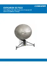
EXPLORER 5075
Brand: COBHAM Pages: 72
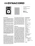
2-WAY SPEAKER MX 12
Brand: Dynacord Pages: 2

SMR 110
Brand: Sencor Pages: 14

MSR2007
Brand: Jensen Pages: 34

FA-40
Brand: Furuno Pages: 4

0020/4995
Brand: TechniSat Pages: 224

MS610
Brand: JBL Pages: 4

UM1A
Brand: Polk Mono Pages: 24

VHF 315 Series
Brand: Garmin Pages: 59

B1474
Brand: Barnett Engineering Pages: 26

Sonoclock 30 SC 3000
Brand: Grundig Pages: 8

TR 2500 DAB+
Brand: Grundig Pages: 16

BOY 55
Brand: Grundig Pages: 4

Cosmopolit 7 WEB
Brand: Grundig Pages: 61

Lumina Series
Brand: SAF Pages: 123

DM588
Brand: Kirisun Pages: 151

RCI-6300F HP
Brand: Ranger Communications Pages: 45


