background image

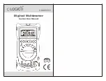
Clamp Meter

With T

Temperature

Page <1>

20/09/10  V1.1

http://www.farnell.com
http://www.newark.com
http://www.cpc.co.uk

Table of Contents

Title

Page

Overview

------------------------------------------------------------------------------------------------------------------------------- 2

Unpacking Inspection  --------------------------------------------------------------------------------------------------------------- 2
Safety Information  ------------------------------------------------------------------------------------------------------------------- 2
Rules for Safe Operation ----------------------------------------------------------------------------------------------------------- 3
International Electrical Symbols  -------------------------------------------------------------------------------------------------- 4
The Meter Structure  ----------------------------------------------------------------------------------------------------------------- 4
Rotary Switch  ------------------------------------------------------------------------------------------------------------------------- 5
Functional Buttons  ------------------------------------------------------------------------------------------------------------------- 5
The Effectiveness of Functional Buttons  --------------------------------------------------------------------------------------- 5
Display Symbols  ---------------------------------------------------------------------------------------------------------------------- 6

Measurement Operation

------------------------------------------------------------------------------------------------------------7

A. DC Voltage Measurement  ---------------------------------------------------------------------------------------------------- 7

B. AC Voltage Measurement  ---------------------------------------------------------------------------------------------------- 8
C. Measuring Resistance  -------------------------------------------------------------------------------------------------------- 9
D. Testing Diodes  ------------------------------------------------------------------------------------------------------------------ 10
E. Testing for Continuity  ---------------------------------------------------------------------------------------------------------- 11
F. Temperature Measurement  -------------------------------------------------------------------------------------------------- 12
G. AC Current Measurement  ---------------------------------------------------------------------------------------------------- 13

Sleep Mode

--------------------------------------------------------------------------------------------------------------------------- 14

Specifications 

------------------------------------------------------------------------------------------------------------------------- 14

A. General Specifications  -------------------------------------------------------------------------------------------------------- 14

B. Environmental Restriction  ---------------------------------------------------------------------------------------------------- 15

Accuracy Specifications

----------------------------------------------------------------------------------------------------------- 15

A. AC Voltage  ----------------------------------------------------------------------------------------------------------------------- 15

B. DC Voltage  ----------------------------------------------------------------------------------------------------------------------- 16
C. Resistance  ------------------------------------------------------------------------------------------------------------------------ 16
D. Continuity Test  ------------------------------------------------------------------------------------------------------------------- 17
E. Diode Test  ------------------------------------------------------------------------------------------------------------------------ 17
F. Temperature  ---------------------------------------------------------------------------------------------------------------------- 17
G. AC Current  ------------------------------------------------------------------------------------------------------------------------ 18

Maintenance

--------------------------------------------------------------------------------------------------------------------------- 18

A. General Service  ----------------------------------------------------------------------------------------------------------------- 18

B. Replacing the Battery  ---------------------------------------------------------------------------------------------------------- 19

Summary of Contents for UT202

Page 1: ...ctional Buttons 5 Display Symbols 6 Measurement Operation 7 A DC Voltage Measurement 7 B AC Voltage Measurement 8 C Measuring Resistance 9 D Testing Diodes 10 E Testing for Continuity 11 F Temperature Measurement 12 G AC Current Measurement 13 Sleep Mode 14 Specifications 14 A General Specifications 14 B Environmental Restriction 15 Accuracy Specifications 15 A AC Voltage 15 B DC Voltage 16 C Resi...

Page 2: ...heck the following items carefully to see any missing or damaged part Item Description Quantity 1 English Operating Manual 1 piece 2 Test Lead 1 pair 3 Point Contact Temperature Probe UT202 only 1 piece 4 1 5V Battery AAA 2 pieces In the event you find any missing or damage please contact your dealer immediately Safety Information This Meter complies with the standards IEC61010 in pollution degree...

Page 3: ...otary switch should be placed in the right position and no any changeover of range shall be made during measurement is conducted to prevent damage of the Meter Do not carry out the measurement when the Meter s back case and battery compartment are not closed to avoid electric shock Do not input higher than 600V between the Meter s terminals and the grounding to avoid electric shock and damages to ...

Page 4: ...ce the battery as soon as leaking appears A leaking battery will damage the Meter International Electrical Symbols AC Alternating Current DC Direct Current AC or DC Grounding Double Insulated Deficiency of Built In Battery Continuity Test Diode Capacitance Test Fuse Warning Refer to the Operating Manual Conforms to Standards of European Union The Meter Structure see figure 1 1 Input Terminals 2 LC...

Page 5: ...ement UT202 only AC current measurement from 0 001A to 400 0A AC Voltage measurement HOLD Press HOLD to enter and exit the Hold mode in any mode the Meter beeps Press and hold HOLD button while turning on the Meter to display full icons MAX Press MAX to start recording and updating of maximum values SELECT Press SELECT button to switch between Ω Ω and C F The Effectiveness of Functional Buttons No...

Page 6: ...ssible electric shock or personal injury replace the battery as soon as the battery indicator appears 4 AUTO The Meter is in the auto range mode in which the Meter automatically selects the range with the best resolution 5 Test of diode 6 The continuity buzzer is on 7 MAX Maximum reading displayed 8 Date hold is active 9 C F The unit of temperature C Centigrade temperature F Fahrenheit temperature...

Page 7: ...ment Operation 1 A DC Voltage Measurement see figure 3 Warning To avoid harms to you or damages to the Meter from electric shock do not attempt to measure voltages higher than 600V AC DC although readings may be obtained The DC Voltage ranges are 200 0mV 2 000V 20 00V 200 0V and 600V To measure DC voltage connect the Meter as follows 1 Insert the red test lead into the terminal and the black test ...

Page 8: ...sting leads from the input terminals Figure 4 Warning To avoid harms to you or damages to the Meter from electric shock do not attempt to measure voltages higher than 600V AC DC although readings may be obtained The AC Voltage ranges are 2 000V 20 00V 200 0V and 600V To measure AC voltage connect the Meter as follows 1 Insert the red test lead into the terminal and the black test lead into the COM...

Page 9: ...g resistance Measurement Operation 4 The resistance ranges are 200 0Ω 2 000kΩ 20 00kΩ 200kΩ 2 000M and 20 00MΩ To measure resistance connect the Meter as follows 1 Insert the red test lead into the terminal and the black test lead into the COM terminal 2 Set the rotary switch to resistance measurement Ω is default or press SELECT button to select Ω measurement mode 3 Connect the test leads across ...

Page 10: ...gure 6 Warning To avoid damages to the Meter or to the devices under test disconnect circuit power and discharge all the high voltage capacitors before testing diodes Use the diode test to check diodes transistors and other semiconductor devices The diode test sends a current through the semicondutor junction then measure the voltage drop across the junction A good silicon junction drops between 0...

Page 11: ...result When diode testing has been completed disconnect the connection between the testing leads and the circuit under test and remove testing leads from the input terminals E Testing for Continuity see figure 7 Measurement Operation 7 Warning To avoid damages to the Meter or to the devices under test disconnect circuit power and discharge all the high voltage capacitors before measuring continuit...

Page 12: ...test and remove testing leads from the input terminals Measurement Operation 8 F Temperature Measurement UT202 Only see figure 8 The temperature measurement ranges are 40 C to 1000 C and 40 F to 1832 F To measure temperature connect the Meter as follows 1 Insert the red temperature probe into the terminal and the black temperature probe into the COM terminal 2 Set the rotary switch to F C and pres...

Page 13: ...00V Use proper function and range for the measurement The measuremnet ranges of current are 2 000A 20 00A 200 0A and 400A To measure current do the following 1 Set the rotary switch to 2 20A or 200 400A 2 Press the lever to open the transformer jaws 3 Center the conductor within the transformer jaw The measured value shows on the display it is a effective value of sine wave mean value response Mea...

Page 14: ...vated by pressing the HOLD button To disable the Sleep Mode function press and hold HOLD button while turning on the Meter Specifications A General Specifications Maximum voltage including transient overvoltage between any terminals and grounding 500V rms Display 3 1 2 digits LCD display Maximum display 1999 Auto Polarity Display Overloading Display OL or OL Battery Deficiency Display Measurement ...

Page 15: ...R H 30 C to 40 C 70 R H 40 C to 50 C 45 R H Storage 20 C to 60 C 75 R H Accurate Specifications 1 Accuracy a reading b digits guarantee for 1 year Operating temperature 23 C 5 C Relative humidity 75 R H Temperature coefficient 0 1x specified accuracy 1 C A AC Voltage Auto ranging Range Resolution Accuracy Overload Protection 2 000V 1mV 1 2 5 600V rms 20 00V 10mV 200 0V 100mV 600V 1V 1 5 5 Remarks ...

Page 16: ...cy Overload Protection 200 0mV 0 1mV 0 8 3 600V rms 2 000V 1mV 0 8 1 20 00V 10mV 200 0V 100mV 600V 1V 1 3 Remarks Input impedance 10MΩ Accurate Specifications 2 C Resistance Auto ranging Range Resolution Accuracy Overload Protection 200 0Ω 100mΩ 1 2 2 600Vp 2 000kΩ 1Ω 1 2 20 00kΩ 10Ω 200 0kΩ 100Ω 2 000MΩ 1kΩ 1 2 2 20 00MΩ 10kΩ 1 5 2 Remarks Input impedance 10MΩ ...

Page 17: ...r test is between 50Ω and 120Ω The buzzer may not beep when the resistance of a circuit under test is greater than 120Ω Range Resolution Accuracy Overload Protection 1mV Display approximate forward voltage drop 0 5V to 0 8V 600Vp Remarks Open circuit voltage approximate 1 48V Range Resolution Accuracy Overload Protection 40 to 1000 C 1 C 40 to 0 C 3 4 600Vp 0 to 400 C 1 3 400 to 1000 C 2 10 40 F t...

Page 18: ...lacement instruction Do not attempt to repair or service your Meter unless you are qualified to do so and have the relevant calibration performance test and service information To avoid electrical shock or damage to the Meter do not get water inside the case A General Service Periodically wipe the case with a damp cloth and mild detergent Do not use abrasives or solvents To clean the terminals wit...

Page 19: ...or are licensed to it No licence is granted for the use of it other than for information purposes in connection with the products to which it relates No licence of any intellectual property rights is granted The Information is subject to change without notice and replaces all data sheets previously supplied The Information supplied is believed to be accurate but the Group assumes no responsibility...

Reviews: