Technics SH-AC500D, Operating Instructions Manual
The Technics SH-AC500D is a versatile audio equipment designed for exceptional sound quality. Enhance your listening experience by easily accessing the Operating Instructions Manual, available for free download on our website. Unlock the full potential of your device with this comprehensive manual, exclusively at manualshive.com.
Share
Download


Reviews:
No comments
Related manuals for SH-AC500D
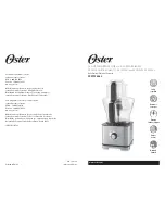
FPSTFP4253
Brand: Oster Pages: 16

TAB Series
Brand: Kingpin Pages: 4
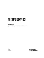
Signal Processing Engineering Educational Device NI...
Brand: National Instruments Pages: 45

EM-2099
Brand: TriStar Pages: 2

LPP
Brand: Cuisinart Pages: 17

Easy Chop
Brand: Inalsa Pages: 4

SC-1146
Brand: Scarlett Pages: 27

KMD3102W
Brand: Beko Pages: 116
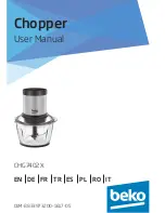
CHG7402X
Brand: Beko Pages: 124

CHG6400W
Brand: Beko Pages: 100

CHG7504W
Brand: Beko Pages: 84

CHP7504W
Brand: Beko Pages: 85

FPP 4102 W
Brand: Beko Pages: 66

CHP6450W
Brand: Beko Pages: 92

CHP5550W
Brand: Beko Pages: 136

CHP5554W
Brand: Beko Pages: 136

Dito K552V203
Brand: Electrolux Pages: 4

Dito 603368
Brand: Electrolux Pages: 2


