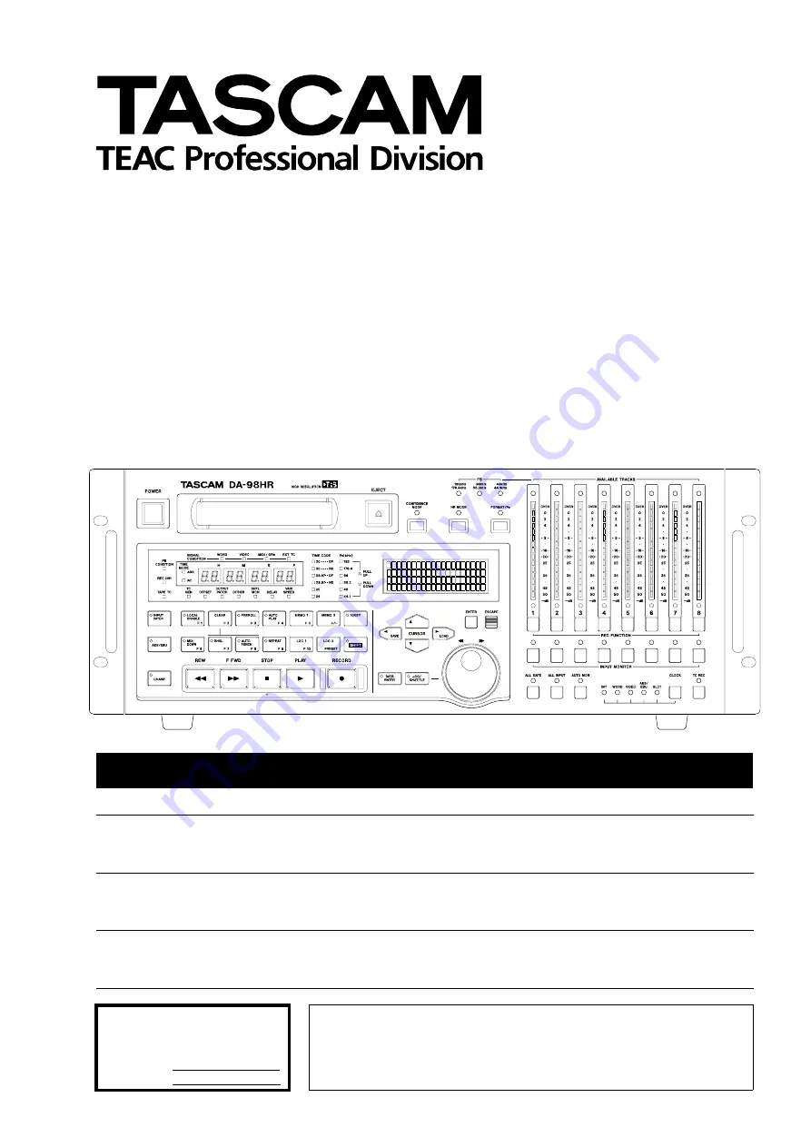
background image

DA-98HR

Digital Multitrack Recorder

OWNER’S MANUAL

CAUTION: TO REDUCE THE RISK OF ELECTRIC SHOCK, DO NOT
REMOVE  COVER (OR BACK).  NO  USER-SERVICEABLE  PARTS
INSIDE. REFER SERVICING TO QUALIFIED SERVICE PERSONNEL.

The exclamation point within an equilateral triangle is intended to alert the user to the pres-
ence of important operating and maintenance (servicing) instructions in the literature
accompanying  the  appliance.

The lightning flash with arrowhead symbol, within an equilateral triangle, is intended to alert
the user to the presence of uninsulated “dangerous voltage” within the product’s enclosure
that may be of sufficient magnitude to constitute a risk of electric shock to persons.

This appliance has a serial number
located on the rear panel. Please record
the model number and serial number
and retain them for your records.
Model number
Serial number

Ü

ÿ
Ÿ

WARNING: TO PREVENT FIRE OR SHOCK

HAZARD, DO NOT EXPOSE THIS 

APPLIANCE TO RAIN OR MOISTURE.

D00539600A

Summary of Contents for DA-98HR

Page 1: ...terature accompanying the appliance The lightning flash with arrowhead symbol within an equilateral triangle is intended to alert the user to the presence of uninsulated dangerous voltage within the p...

Page 2: ...ould be used and be sure to re fit the fuse cover IF IN DOUBT CONSULT A COMPETENT ELECTRICIAN TO THE USER This equipment has been tested and found to comply with the limits for a Class A digital devic...

Page 3: ...g structure grounding of the lead in wire to an antenna discharge unit size of grounding conductors location of antenna discharge unit con nection to grounding electrodes and requirements for the grou...

Page 4: ...s 25 4 3 Assigning menus to function keys 25 4 3 1 To assign a menu screen to a key 25 4 3 2 Recalling an assigned menu function 25 4 4 Using the function keys as number keys 25 5 Monitoring modes 5 1...

Page 5: ...machine offset 52 8 4 3 Setting machine offset on the fly 52 8 4 4 An example of setting offsets 52 8 4 5 Clock mode 53 8 5 Digital dubbing 54 8 5 1 Synchronized formatting 54 8 5 2 Recording while f...

Page 6: ...2 2 Checking error rates 84 12 2 1 Checking head time 84 12 2 2 Checking head search time 84 12 3 Memory backup 84 12 4 User setups in RAM 85 12 4 1 Saving user setups 85 12 4 2 Loading user setups 85...

Page 7: ...m 6 ft long x 1 This manual x 1 Warranty card x 1 Quick Start guide x 1 HC 8 cleaning tape 1 2 Features Key features of the DA 98HR include TASCAM exclusive high performance high wear resistive rotary...

Page 8: ...ns that you will not necessarily perform every day but are necessary for the successful operation of the DA 98HR 8 DTRS synchronization You should read this section when you use the DA 98HR with other...

Page 9: ...owing you to monitor off tape as recording progresses Since this monitoring is not synchronized exactly with the source inputs gapless punch in and punch out is not possible in confidence mode For ful...

Page 10: ...s designed for use with Hi8 video cassettes You cannot use any other kind of tape with the DA 98HR There are two basic types of Hi8 tape MP and ME Each has its own particular characteristics and mer i...

Page 11: ...tomatically eject any tape thinner than recommended Never attempt to use a tape with the DA 98HR that has previously been used in video equipment NOTE You cannot cut and splice DTRS 8mm tapes for edit...

Page 12: ...nd indi cator allow selection and viewing of the status of this monitoring mode For a full explanation of confidence monitoring see 5 3 Confidence mode 5 Fs indicators These indicators 192kHz 176 4kHz...

Page 13: ...access to the input patchbay screen 6 3 3 Selecting input sources The indicator shows that the patchbay is in use even when the screen is not displayed It goes out when all inputs are normalled D AES...

Page 14: ...ey S is pressed this key becomes a function key L RHSL F7 key and indicator This key and indicator allow selection of the rehearsal mode in auto punch in and out 6 6 Punch in and punch out When the 10...

Page 15: ...choices within the menu The left and right keys and are used for cur sor navigation See 4 Menu operations for details of how to use these keys in menu operations When the SHIFT key S is active the le...

Page 16: ...and input monitoring depend ing on the transport mode For a full treatment of monitoring modes on the DA 98HR see 5 Monitoring modes j CLOCK key and indicators This key and these indicators allow you...

Page 17: ...e self terminating THRU con nector echoes messages received at the IN See 9 7 Video resolution for details of video sync operation o WORD SYNC IN OUT THRU AUTO TERM These BNC connectors are used to ca...

Page 18: ...ght channels of digital audio to and from the DA 98HR in TEAC Digital Interface Format TDIF 1 v METER UNIT This connector carries power and signals to drive 8 channels of the optional MU 8824 24 chann...

Page 19: ...eady made cables However we rec ognize that every situation has its own unique features and there are occasions when a special cable must be made Before starting to make the cable we suggest you conta...

Page 20: ...unit This signal should be a 1 Vp p composite signal If other equipment such as other DTRS units also need the video frame reference clock the signal received at the VIDEO IN is echoed at the VIDEO T...

Page 21: ...it or digital mixing console incor porating remote control facilities which may also be connected in a chain with multiple DTRS units 3 4 1 Multiple DTRS units Use a TASCAM PW 88S cable when connectin...

Page 22: ...igital audio device In this case the master unit will have its clock source set to WORD and the slave will receive its clock from the master unit through the SYNC IN s 3 4 3 Meter unit MU 8824 The opt...

Page 23: ...erefore used if you enter the wrong menu by mistake For a full description of the menu tree see the Quick Start guide or 11 Menu and parameter reference 4 1 4 Editing values When a parameter has been...

Page 24: ...also possible to use the dial to change values This can be a convenient way of making larger changes to numeric values 1 Press the DATA ENTRY key b so that the indi cator lights Note that if the JOG...

Page 25: ...e likely that you will find yourself using a few of the same menu functions many times for instance manual adjustment of punch points and many of the menu functions only rarely for instance whether th...

Page 26: ...s parameter should be set using the and keys not the num ber keys The following is a step by step guide to entering a value 1 minute and 5 seconds into the Locate Pre roll parameter 7 1 3 Setting the...

Page 27: ...sually want to monitor the program material recorded on the tape However there are times when you want to monitor the source input rather than the recorded signal even in play mode The following table...

Page 28: ...utput from there 1 From menu group B move the cursor to Out Patch and press ENTER 2 Use the and keys to select the track Trk which will be routed to the output channel Use the and keys to change the v...

Page 29: ...cks 2 Turn off AUTO MON mode and make sure that the ALL INPUT switch is off NOTE Using confidence mode it is possible to monitor some tracks off tape during recording while monitoring the input source...

Page 30: ...iate error message is shown and the screen flashes e g Fs unmatch for mismatched sampling frequencies or TDIF dubbing cable not connected if a TDIF digital source has been selected but is not properly...

Page 31: ...word sync clock source using the CLOCK key All AES EBU sources must be at the same fre quency etc before they can be selected as clock sources An error message will be shown on screen if they differ...

Page 32: ...he base frequency the number of tracks which are available for recording varies according to the sampling frequency selected The AVAILABLE TRACK 8 indicators above each track meter show the current st...

Page 33: ...sible to format tapes on a number of DTRS units simultaneously For details see 8 5 1 Syn chronized formatting 6 2 3 Aborting the format process To abort the process before formatting actually takes pl...

Page 34: ...ich naturally does not have any sources and therefore is always repre sented by a 2 Use the and keys to move the cursor along a line 3 Use the and keys to change the parame ter value 4 To move between...

Page 35: ...the RECORD FUNCTION on all armed tracks or using the ALL SAFE key g This will prevent you from accidentally hitting the RECORD key and going into record mode overwriting what you have already recorde...

Page 36: ...g the punch in 4 When ready for the take press the AUTO PUNCH key M so that the indicator flashes Now when PLAY is pressed the unit records at the punch in point and drops out at the punch out point 6...

Page 37: ...ut for 1 100 frame units it is sf on the bot tom line of the display and using the and keys to change between them 4 Use the and keys to select the field hours minutes seconds or sub frame units that...

Page 38: ...or punch recording Very often while rehearsing a punch in you will not want to run the tape all the way to the punch out point an entry is missed or a mistake is made early on in the take In these cas...

Page 39: ...ed above 4 If you are satisfied with the punch in follow the steps below otherwise press LOC 1 to return to the punch in point press the AUTO PUNCH key so that the indicator flashes and repeat the tak...

Page 40: ...wn will change appropriately Press ESCAPE when you have finished checking 2 To edit the points move the cursor to Memo 1 or Memo 2 and press ENTER to select the location point to edit 3 Use the and ke...

Page 41: ...Press the function key to which you want to assign a memory The display screen shows the time of the location memory after you have stored it to a function key You can continue to press function keys...

Page 42: ...arts playing until the second location point rewinds to the first location point and plays again This process is repeated While the tape position is between the two location points the REPEAT indicato...

Page 43: ...the key and then pressing the key If ALL has been selected for the track then all track delays will be reset to zero You can also use the function keys to enter the value directly as described in 4 4...

Page 44: ...the center position the shuttle speed changes following these values relative to normal speed 0 25 0 5 1 0 2 0 4 0 8 0 The 1 0 speed is only available when shuttling in the forward direction Shuttle...

Page 45: ...M boards may or may not permit setting of ref erence levels from this screen Consult the board s docu mentation for details 7 8 Meter modes The DA 98HR peak bargraph meters can be custom ized to suit...

Page 46: ...interface units or optional slot boards for the DA 98HR which allow connection to other equip ment e g the IF 88SD which allows conversion between SDIF 2 and TDIF 1 formats The DA 98HR should be conn...

Page 47: ...2 Use the and keys to change between dual line and high speed 7 10 4 Cbit mode When receiving AES EBU data the header informa tion the Cbits in the audio data contain informa tion about the audio form...

Page 48: ...way you will be able to make an instant assessment of the effects of the different dither settings on your program material 7 12 1 Selecting dither settings 1 Enter menu group 1 move the cursor to Di...

Page 49: ...NTER 2 To clear the current message use the and keys to move the cursor to CLEAR and press the ENTER key 3 Use the and keys to move the cursor to the input field and press the and keys to select a cha...

Page 50: ...ithout ABS time recorded on them make syn chronization impossible To synchronize multiple DTRS units all the tapes in each unit must be formatted using the same base sampling fre quency or synchroniza...

Page 51: ...If the bottom line does not show ABS that is if it shows TC press the key so that ABS is displayed 2 On each slave unit press the CHASE key E The CHASE indicator starts to flash 3 Press any of the tr...

Page 52: ...ancelling machine offset To cancel machine offset simply set the offset value to 00 00 00 00 1 Press and hold down the key and press the key to reset the value in the Machine Offset menu see above Mac...

Page 53: ...DTRS units when TC time mode see 9 2 Tape timecode mode is selected There are two settings Auto and Individual individual Note that this is only relevant when the time mode is set to TC rather than AB...

Page 54: ...the digital inputs on the target slave this differs between models for the DA 98HR see 6 3 3 Selecting input sources 6 Put the target slave machine into CHASE mode 8 2 3 Master slave settings CHASE mo...

Page 55: ...ss RECORD on the master All slave units CHASE indicators will light steadily and the tapes will start to be formatted in synchronization 8 5 2 Recording while formatting As with a single machine forma...

Page 56: ...code and is shown whenever a SMPTE EBU timecode value is used rather than the ABS value The timecode may be internally generated or received from an external source It can be SMPTE EBU received and tr...

Page 57: ...e as selected in 9 4 Selecting the frame rate NOTE If you are using ABS timings as timecode the hours min utes and seconds of the ABS time will correspond to the converted timecode unless the frame ra...

Page 58: ...scribed below 1 Go to menu group E and move the cursor to Tape TC 2 Start playing the tape 3 The tape timecode value is displayed on the bottom line together with the system frame rate If TC Track has...

Page 59: ...and keys to select the source of the timecode as Generator TC 6 Go to menu group 8 move the cursor to Gen Start generator start time and press ENTER 7 Use the and keys to select the field hours minut...

Page 60: ...may want to use the assembly function when the first part of a tape contains timecode and you want to stripe the rest of the tape with timecode that follows on seamlessly from the originally recorded...

Page 61: ...nized with the DA 98HR a timecode generator video synchronized with the DA 98HR NOTE Do not use any timecode recorded on the DA 98HR s dedi cated subcode track as the timecode master when transfer ri...

Page 62: ...tape stripe frame rate and cannot be changed 9 4 1 Pull up and pull down Fs shift When working in film post production with NTSC telecine equipment the frame rate of film 24 fps and the NTSC color fr...

Page 63: ...e separate offset settings but can use the master DA 98HR s offset 9 5 3 Timecode output format This Fast LTC function controls the way in which timecode is output when fast winding the tape or if shu...

Page 64: ...n a DA 98HR unit has its machine ID set to a value other than 1 there is a conflict when the CHASE key is pressed You must determine whether the chase mode refers to timecode or to the DTRS sync and t...

Page 65: ...ture the offset value Once the offset value has been captured successfully the display will change to show the captured offset value on the bottom line After the timecode offset has been entered in th...

Page 66: ...master the difference 4 frames is the relative difference between the master and the slave To view the absolute and relative differences between master and slave machines 1 Go to group menu E 2 Move t...

Page 67: ...l as SYNC and have TC rather than ABS selected as the timing reference this default behavior can be overridden using the function described here 1 Go to menu group 4 move the cursor to TcChs Rec timec...

Page 68: ...order to assist the synchronization process To specify this explicitly 1 Go to menu group 3 move the cursor to VideoRef and press ENTER 2 Use the and keys to set this value to either Auto the default...

Page 69: ...see 8 DTRS synchroni zation will always be valid 10 3 Use with 9 pin external control The RS 422 control allows the DA 98HR to be con trolled by a number of different editor controllers in the same wa...

Page 70: ...d NOTE This delay is also used for controlling the timing of the mon itor switching 10 3 4 Cue up tally When the DA 98HR is in 9 pin protocol mode and a locate command is received the transport locate...

Page 71: ...Map track mapping and press ENTER The lines above show the analog and digital tracks to which the DA 98HR tracks on the bottom line are currently assigned The terms analog and digital used here have n...

Page 72: ...er to it as a channel number and is not connected with the Machine ID 8 2 2 Setting machine ID To set the MIDI ID 1 Go to menu group 7 move the cursor to MIDI ID and press ENTER 2 Use the and keys to...

Page 73: ...HR When the DA 98HR has located and starts playback or recording the MTC is transmitted back to the sequencer which locks in and starts at the correct point In this way though the DA 98HR is the timec...

Page 74: ...ot board inputs S or digital inputs D or muting M 6 3 3 Selecting input sources Vari Speed Enabled Amount Fix Vari 6 0 through 6 0 default is 0 0 7 5 Vari speed pitch control Memo 1 Time value Default...

Page 75: ...dB Input Output view only 7 7 Reference levels Menu item Parameter s Values Reference Machine ID Machine ID for synchronization 1 through 16 8 2 2 Setting machine ID Machine Offset Time value to sub...

Page 76: ...rate TC track rate view only 30 DF 30 NDF 29 97 DF 29 97NDF 25 F 24 F 9 4 Selecting the frame rate TC I O Timing Input and out put timing refer ence for timecode Analog Digital for both input and out...

Page 77: ...ble enable 10 3 7 Timecode track mapping Fast Wind Speed Referenced to play speed x 100 x 8 10 3 5 Fast wind speed Cueup Tally Message to remote Stop Still 10 3 4 Cue up tally Menu item Parameter s Va...

Page 78: ...nding on the setting made in the Tape TC Mode menu 9 2 Tape timecode mode 9 3 Recording time code Tape TC Mode Tape timecode source TcTrack ABS ABS Ofsb ABS 13 ABS 23 b If the ABS Ofs Absolute timing...

Page 79: ...re grouped together 6 1 2 Setting the AES EBU channel for the word sync source Menu item Parameter s Values Reference Output Patch source and channel track assignment Normalled one to one corresponden...

Page 80: ...nu Moving the cursor to the menu item will display the relevant value on the bottom line of the display 9 Operations related to timecode Tape TC Gen TC Abs Diff 9 6 9 Absolute and relative difference...

Page 81: ...Shift Mode 8 Function Key Mode 7 Gen TC E Generate Mode 8 Generate Start Time 8 Input Board Info D Input Patch 0 Io Board Clk Range D Level Meter Mode 2 Locate Position 7 Locate Pre roll 0 Machine ID...

Page 82: ...M DA 98HR TC Frame Mode 5 TC Frame Mode 8 TC Record Enable 6 TC Record Source 8 TC Timing 5 TDIF Word Length 2 Time Mode 3 Timecode Offset 4 Track Delay Time 0 Track Mapping 6 User bits D Vari Speed 0...

Page 83: ...r experience with the DTRS system for cleaning and maintenance schedules See Checking head time on page 84 below for details of how to check head usage time The above cleaning cycle timings are based...

Page 84: ...and transport cleaning Remember not to clean the heads more than 5 times in a row NOTE If after trying different tapes and cleaning the heads you still see many errors you should contact a TASCAM ser...

Page 85: ...o menu group 9 move the cursor to Setup and press ENTER 2 To load the setup memory into the current memory make sure the bottom line shows Load 3 Move the cursor to 1 2 or 3 and press the key 4 Press...

Page 86: ...e erased 12 5 1 Saving settings to tape 1 Press the SHIFT key so that the indicator flashes 2 Press the SAVE key 3 Press the ENTER key to confirm the save oper ation The tape rewinds to the start of t...

Page 87: ...ver system version Front ver front panel software ver sion or Servo ver servo control soft ware version field The version number of the appropriate software will be shown on the bot tom line of the d...

Page 88: ...s REMOTE IN SYNC IN connector s Up to 6 DTRS units can be controlled using one RC 898 controller The first unit in the chain should be a DA 98HR The first DTRS unit in the chain should be given Machin...

Page 89: ...erwrite Head construction 2 x record 2 x playback Tape type Hi8 MP tape Hi8 ME Maximum recording time 108 min using P6 120 tape Other features Up to 16 DTRS units can be synchro nized giving up to 128...

Page 90: ...ations CONTROL I O 37 pin D sub Cross fade time 10ms to 200ms 10ms increments Track delay 200 to 7 200 samples 4 to 150 ms in single unit increments Can be set in samples or ms Offset 2 hours to frame...

Page 91: ...3 0 1B 1A 19 18 17 16 15 c4 0 0 0 0 1F 1E 1D 1C c5 0 26 25 24 23 22 21 20 c6 0 2D 2C 2B 2A 29 28 27 c7 0 34 33 32 31 30 2F 2E c8 0 3B 3A 39 38 37 36 35 c9 0 0 0 0 3F 3E 3D 3C c10 0 46 SEARCH 45 VARIAB...

Page 92: ...6 SELECTED TIME CODE SOURCE 45 TIME STANDARD 44 COMMAND ERROR LEVEL 43 COMMAND ERROR 42 RESPONSE ERROR 41 UPDATE RATE 40 SIGNATURE r11 0 4D RECORD STATUS 4C RECORD MODE 4B FAST MODE 4A STOP MODE 49 VE...

Page 93: ...te ON x x Note OFF x x After Key s x x Touch Ch s x x Pitch Bender x x 7 9 10 11 x o Other x x Control Change True 0 127 Prog x x Change True 1 128 System Exclusive o o 1 System Song Pos x x Song Sel...

Page 94: ...achine offset of a slave machine chasing to a master via a SYNC IN connection the master s chase cannot be set of course The limits of this parameter are 02 00 00 00 If a value over or below these lim...

Page 95: ...wo data bytes destination and source destination is the tape track number 1 00h through 07h source is either the slot input channel number 1 00h through 07h the digital input channel number 7 08h thro...

Page 96: ...62 head search time 84 head time 84 MEMO 1 and MEMO 2 40 tape TC 58 Cleaning 83 CLEAR key 14 Clock mode 53 range with slot board 31 selecting word sync 31 source in a digital studio 9 video 69 Clock...

Page 97: ...ISABLE F1 key and indicator 13 Locating to a function key memory 41 Location and playback 42 Location memories 41 storing 41 Location pre roll time setting 40 M Machine ID and master slave settings 50...

Page 98: ...Reference levels 45 Rehearsing the punch in 38 Relative difference 66 Remote control units 88 REMOTE IN SYNC IN 18 Remote track arming 72 REPEAT F9 key 14 Repeat function 42 Repeat play 42 Resetting...

Page 99: ...tput timing 63 rechasing 66 recording 58 recording from an analog recorder 61 recording from external sources 61 recording using the generator 59 selecting source 58 setting offset 64 setting offset o...

Page 100: ...ns Meadow The Croxley Centre Watford Herts WD1 8YA U K TEAC DEUTSCHLAND GmbH Phone 0611 71580 Bahnstrasse 12 65205 Wiesbaden Erbenheim Germany TEAC FRANCE S A Phone 01 42 37 01 02 17 Rue Alexis de Toc...

Reviews: