background image

SSU

UN

NSSTTAARR M

MAAC

CH

HIIN

NEERRYY C

CO

O..,, LLTTD

D..

M

ME

EE

E--0

06

61

11

11

17

7

R

User’s
Manual 

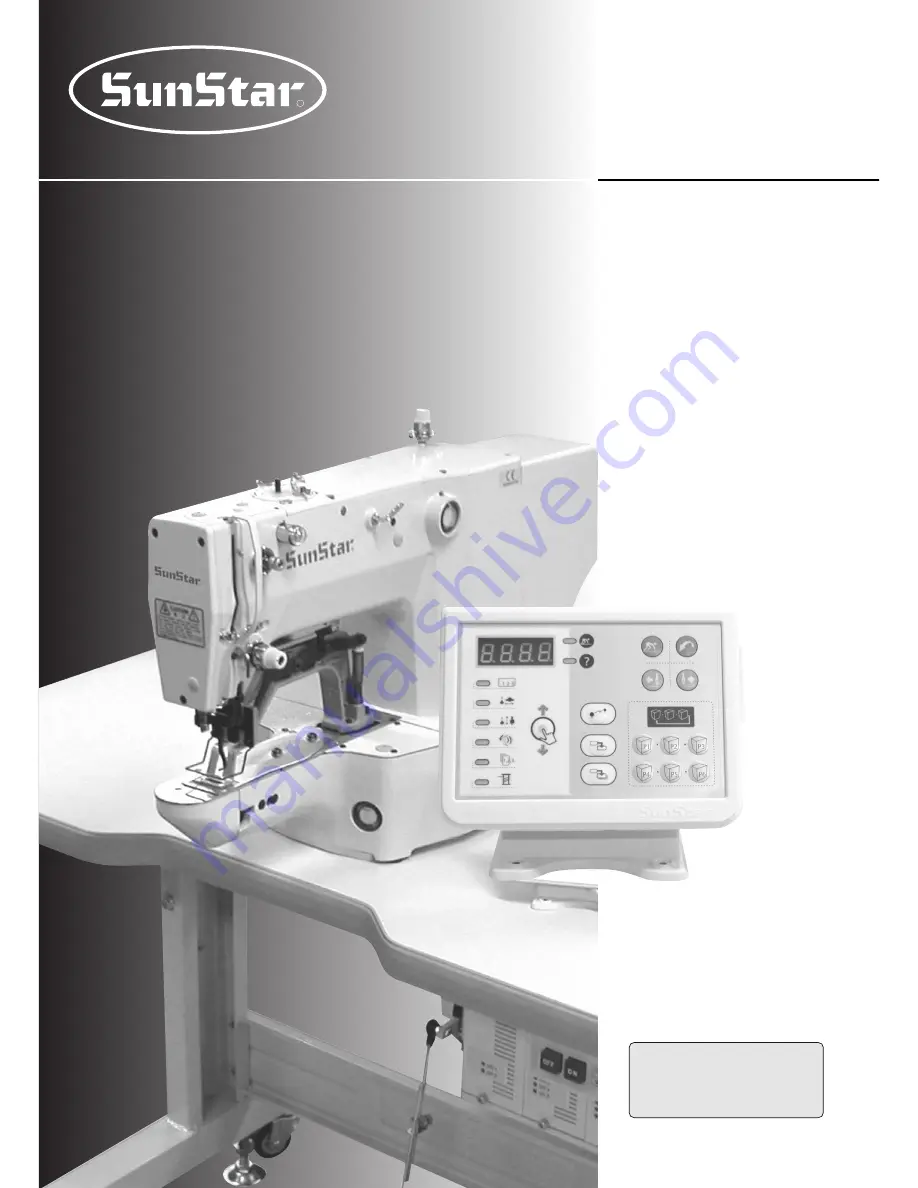
SPS/E-Bartacking Series
SPS/E-Button Sewing Series

Electronically Controlled 

Bartacking Machine

(Electronic Control Part)
Electronically Controlled

Button Sewing Machine

(Electronic Control Part)

1) For proper use of the machine,

thoroughly read this manual before use.

2) Keep this manual in a safe place for

future reference in case the machine
breaks down.

Summary of Contents for SPS/E-BR1201K

Page 1: ...eries SPS E ButtonSewingSeries Electronically Controlled Bartacking Machine Electronic Control Part Electronically Controlled Button Sewing Machine Electronic Control Part 1 For proper use of the machine thoroughly read this manual before use 2 Keep this manual in a safe place for future reference in case the machine breaks down ...

Page 2: ... functions high performance powerful operation enhanced durability and more sophisticated design to meet a number of user s needs 2 Please read this user s manual thoroughly before using the machine Make sure to properly use the machine to enjoy its full performance 3 The specifications of the machine are subject to change aimed to enhance product performance without prior notice 4 This product is...

Page 3: ...ixing device Sunstar Pattern System Series Classification E Direct Drive Type Servo step motor used Bartack Sewing Machine BR Full rotary hook BS Half rotary hook SPS E BS1202 0 1 Button Type 01 Small Size Button Mechanical Type Wiper 02 Large Size Button Mechanical Type Wiper 03 Small Large Size Button Solenoid Type Wiper Sunstar Pattern System Series Classification E Direct Drive Type Servo step...

Page 4: ...tage 11 3 3 Control Box LED Check 11 4 SM Operation 1 Basic 12 4 1 Names and Functions of Keys in the Operation Box 12 4 2 Setting Item Data 13 4 3 Checking Pattern Shape 16 4 4 Sewing 16 4 5 Changing Sewing Pattern 17 4 6 Lower Thread Winding 17 5 SM Operation 2 Advanced 18 5 1 User Program 18 5 2 Sewing using Combination Function 19 5 3 Sewing using Lower Thread Counter 20 5 4 Precautions 21 6 U...

Page 5: ... 7 4 Other Functions 35 7 5 Installing and Replacing ROM 36 7 6 Pattern download from PDA or PC 41 7 7 Pattern download from CF card 42 8 Error List 44 9 How Select the Sewing Pattern List and the Sewing Lange 47 9 1 BS R 1201 Series 47 9 2 BS R 1202 Series 48 10 BASIC MANUAL 49 ...

Page 6: ... ⓑ Dust and moisture stains and rusts the machine Install an airconditioner and clean the machine regularly ⓒ Keep the machine out of the sun If the machine is exposed in direct ray of light for a long time transformation of color and shape can be happened ⓓ Leave sufficient space of more than 50cm behind and on the right left and back side of the machine for repairing ⓔ Do not operate in explosiv...

Page 7: ...n ⓘ Do not use several motor per a electric outlet ⓙ If possible install the machine away from loud noise such as high frequency welding machines ⓚ Be careful when the upper feed plate comes down to press Otherwise the finger or hand height be hurt at smacking 1 4 Machine Operation Caution Caution ⓐ Safety label It describes cautions during operating the sewing machine ⓑ Thread take up cover It pr...

Page 8: ... 뽑 고 나서 360초간 기다린 후 여십시오 Warning 1 6 Caution Mark Position CAUTION 경 고 Do not operate without finger guard and safety devices Before threading changing bobbin and needle cleaning etc switch off main switch 손가락 보호대와 안전장치 없이 작동하지 마십시오 실 보빈 바늘교환시나 청소전에는 반드시 주 전원의 스위치를 꺼 주십시오 WARNING 경 고 Hazardous voltage will cause injury Be sure to wait at least 360 seconds before opening this cover after turn off m...

Page 9: ...spm with an external switch R θ method step motor is used Up to 10 000 stitches Up to 99 patterns default 32 patterns 20 200 adjustable by 1 P ROM 550W direct drive AC servo motor standard power 600 W 600VA 5 40 20 80 Single phase 100 240V 3 phase 200 440V 50 60Hz SPS E BS1201H SPS E BS1201M SPS E BS1201L SPS E BS1201K SPS E BS1201M HP SPS E BR1201M SPS E BR1201L SPS E BR1201K Heavy materials Gene...

Page 10: ...tage section before changing the voltage Single phase connection 100V 110V 120V 200V 220V 240V 3 phase connection 200V 220V 240V 380V 이 기계의 전기 사양은 공장 출고 시 아래의 표기되로 결선되어 있습니다 V 단상 1 Phase 삼상 3 Phase 110V 120V 220V 240V 220V 240V V V The Electric Specification of This Machine is Connected Under Marked V In case of 3 phase 380V it is necessary to install an additional trans box on the table check it ...

Page 11: ...N5 CN4 CN3 CN1 220V CN6 CN7 JP1 CN6 CN7 JP1 Incorrect setting of the voltage connector may damage the control box Caution 3 3 Control Box LED Check LED displays the power supply status to each board Therefore when problems occurs it is easy to identify where the problems were developed 1 E SERIES LED LED Power Supply Status Power Supply Status LED1 LED5 Digital Board 5V Input Main Shaft Board 220V...

Page 12: ...ror Press to select item At every press item changes as below Selected item will be lighted Pattern No X Scale Y Scale Sewing Speed Counter Thread winding Sewing ready lamp Ready key Reset key Forward Back Communication Serial download Note 1 CF card download Note 1 Register LED display Error lamp Set pattern No X scale Y scale Speed Production counter Lower thread winding Select Note 1 To use the...

Page 13: ...er C Set X Scale Pattern No X Scale Y Scale Sewing Speed 1 Press to display NO 2 Press to display 2 on the screen setting pattern No 2 Refer to the program list BACK FORWARD SELECT 1 Press to display item X Scale 2 Press to set within the range of 20 200 BACK FORWARD SELECT 1 For direct connection type if the head is laid down on the side while the power is on oPEn will appear If READY key is on a...

Page 14: ...ht within the scope of H 10 H 17 by pressing and 3 Press the key to save the changed values and make the machine return to the ready mode READY BACK FORWARD Communication ready b Adjustment of descending height 1 Press the key to display the height of the presser foot when it descends 2 Set the height within the scope of L 1 L 17 by pressing and 3 Press the key to save the changed values and make ...

Page 15: ...n The machine will be on standby You can press to confirm the setting SELECT READY Check the pattern number before starting the machine 1 If is pressed with the pattern number 0 default status the machine will move back to original point Use it to check the machine original point 2 If you select a pattern that contains no data error Er01 will appear Select other pattern READY Caution ...

Page 16: ...ARD 1 Place the work material on the presser plate 2 Pedal 1st step to bring down the presser plate Take your foot off the pedal to lift the plate 3 Pedal 2nd step with the presser plate down and the sewing will start 4 When the sewing is completed presser plate will go up and move to the sewing starting point 1st Step 2nd Step 1st step pedal switch 2nd step pedal switch 1 Make sure to check the p...

Page 17: ...tch to 2nd step again Winding will stop 5 Press to end winding CAUTION When using hole fixing device if you shift to bobbin winding mode and pres READY the pin hole will go down and the presser plate will move to the original point READY READY SELECT 1 Press READY light will turn off 2 Press to display item NO 3 Set B F items in 4 2 and move to the item of checking pattern shape SELECT READY Durin...

Page 18: ...26 in B of the above and follow the rest of the procedures F After registration turn off the power and turn it on again READY BACK FORWARD SELECT BACK FORWARD SELECT P1 SELECT P P01 3 50 P 80 1800 Ex Registering the following set up as P1 Pattern Number 3 X scale 50 Y scale 80 Maximum speed limit 1800spm Reg No P01 P02 P03 P04 P05 P06 P07 P2 P1 P6 P5 P4 P3 P2 P1 P08 P09 P10 P11 P12 P13 P14 P15 P16...

Page 19: ...wing using Combination Function You can list the pre registered user programs P1 P26 in Cnb1 and Cnb2 and change the pattern in the order of the programs on the list Maximum number of program combinations you can register in Cnb1 and Cnb2 is 30 1 Registration of Combinations Ex Combine P1 P2 and P3 in that order and register the combination in Cnb1 A Turn on the power pressing and B Press and then...

Page 20: ...lly shift to the next pattern within the combination for example Cnb1 BACK FORWARD READY BACK FORWARD 5 3 Sewing using Lower Thread Counter Workload counter can also be used as a lower thread counter If you are repeating the same pattern the machine will stop when it reaches the sewing limit of one bobbin At this time the lower thread counter should be set at reduction mode A Press with the READY ...

Page 21: ...press twice to bring the needle to the right position D Do NOT turn off the power with the needle bar down READY Sewing speed for different work E Set the sewing speed according to the above table in order to prevent thread break from heat F For materials like underwear lower the needle bar height in order to prevent jump stitch refer to Adjusting Needle Bar Height Denim 8 sheets Denim 12 sheets C...

Page 22: ... power pressing and 2 For changing general sewing related functions press 3 For changing servo motor control related functions press and operate the memory switch Turn off the power and back on again after changing the memory switch set up B A RESET READY A Turn on the memory switch and press You will see A 01 on the screen B Press and you will see the present set up C Press to change the set up v...

Page 23: ...ging to 900 spm D Press 2nd stitch speed 900spm is displayed E Press to change to 2 12 changing to 1 200 spm F Register the set up using READY FORWARD SELECT FORWARD READY FORWARD Ex Changing the 1st stitch 400 900 rpm and the 2nd stitch 900 1 200 rpm A 02 2 09 1 04 1 09 A 02 2 12 1st stitch 2nd stitch 3rd stitch 4th stitch 5th stitch Scope 400 900 400 2700 400 2700 400 2700 400 2700 Default 400 s...

Page 24: ... possible C Press to change 1 in ⓑ to 0 D Press to change 1 in ⓐ to 2 E Press to change 1 in ⓑ to 0 F Register the set up using READY BACK SELECT BACK READY FORWARD Ex Inactivating calling of patterns 1 and 2 ⓐ ⓑ A 03 02 1 01 1 01 0 A 03 02 0 Ex Changing production counter addition mode to lower thread counter reduction mode A Turn on the memory switch and press to display A 05 on the screen B Pre...

Page 25: ...ⓐ part 0 holding device OFF ⓐ part 1 holding device ON C Press to change ⓐ 0 to 1 D Register the set up using READY FORWARD READY FORWARD ⓐ A 32 A 32 0 1 Ex Using a separated pedal A Turn on the memory switch and press to display A 33 on the screen B Press to display the present set up value ⓐ part 0 integrated pedal ⓐ part 1 separated pedal C Press to change ⓐ 0 to 1 D Register the set up using R...

Page 26: ...on after trimming 0 70 0 1 A 14 Setting whether to use electronic wiper 0 OFF 1 ON A 15 Faster moving of presser foot after trimming 0 OFF 1 ON 1 A 16 Setting search for original point after certain amount of sewing 0 OFF 0 after amount set in A 17 1 ON A 17 Number of automatic search for original point 0 1000 1000 4 A 18 Time for electronic wiper ON 4 1024 ms 100 ms 4 ms A 19 Canceling trimming 0...

Page 27: ...e memory switch pressing P3 C 01 C 02 When the electronic wiper is used A15 1 set the standby time from trimming to wiper motion Set the operating angle of the trimmer solenoid 1 255 ms 1 250 degrees 165 ms 40 degrees 1 ms 1 degrees No Functions and Description Scope Default Unit ...

Page 28: ...ion Synchro sensor detection time Overload detection time Motor fixing is possible impossible while the machine is not in operation Direction of servo motor rotation Original point sensor detection time pos_spd end spd2 StopDelay DIST1 KC1A KC1C KF1A KF1C spd_unit KH1 KH2 accelA accelB accelC accelD Inertia SPMUPPER UPPosition IND_REFM KF2A KF2C PULY_SIZEM CutStartM CutEndM SLockTmM OvLoadM HOLD_F...

Page 29: ...edal The higher this value the higher acceleration to the target speed but speed fluctuation may also increase when reaching the target speed B 18 accelC Represents level of speed reduction by pedal The higher this value the faster reduction of speed to the target speed but speed fluctuation may also increase when reaching the target speed Examples of the shaded functions Unable to come to sudden ...

Page 30: ...oard Step board Main shaft board No F1 Capacity 15A Use Main power protection Inside C B C B Rack Structure Turn off the power before cleaning the machine to prevent accidents associated with mistaken machine operation Caution To prevent electric shock wait 5 minutes after power off to open the cover Make sure to turn the power off when opening the control box Change to a fuse of a designated capa...

Page 31: ...tep Motor Drive and Original Point Sensor 1 Turn on the Machine Test and press 2 Press the relevant key and the needle will move 3 X axis original sensor signal and Y axis original sensor signal will appear on X scale lamp and Y scale lamp respectively 4 You will know it is OK if the above two lamps are on when the needle is on the left upper side of the feed plate 5 Since the clamp shaft does not...

Page 32: ...ing Main Shaft Motor 1 Run the Machine TEST and then press and to display t 03 2 Press 3 Press and the motor will rotate Speed of the main shaft motor will be displayed on the screen Press again to stop 4 Adjust the speed using and keys 5 Press to end the test SELECT BACK FORWARD READY READY READY BACK FORWARD 5 Testing Encoder 1 Run the Machine TEST and then press and to display t 04 2 Press 3 Ro...

Page 33: ...ress to light on all of the 8 auxiliary output J11 on digital circuit board Press again to turn off all of them 4 Press to end the test SELECT READY READY READY BACK FORWARD 1st Step 2nd Step Aux1 switch Aux2 switch Aux output On Off End of test 6 Testing Synchronizer 1 Run the Machine TEST and then press and to display t 05 2 Press 3 Rotate the pulley manually The screen will display the rotation...

Page 34: ...ype SELECT READY BACK FORWARD Aux8 input Aux7 input Aux6 input Aux5 input Aux4 input Aux3 input Aux2 input Inputting the external convering of function key 10 Clamp motor motion test 1 Run the Machine TEST and then press and to display t 09 2 Press 3 Press to set the delay times for clamp moving up and down Use and keys to change the delay time 4 Press to end the test RESET BACK FORWARD SELECT REA...

Page 35: ...ll soon see the initial screen CAUTION Memory switch initialization will remove all of your memory switch set ups BACK FORWARD 2 Inertia Tuning The controller performs an automatic inertia tuning suitable to the machine load Do not perform this function unless tracking of the sewing speed is too slow or the machine stops at one stitch later 1 Press and at the same time to turn the power on 2 The f...

Page 36: ...turning on the power represents machine model and its version 16 bH Sticker Usually 8 digits but may be different according to design Ex bc000928 bj000930 Scalable pattern ROM Sticker Differences in programs and functions by type Classification B1201HA B1201H B1201M B1201MHP B1201L B1201K B1202 Pneumatic Heavy Ordinary Hole fixing device Light Knitwear Buttoning 2 700 3 200 3 200 3 200 2 500 2 500...

Page 37: ...stalled accurately on the socket 4 When removing the existing ROM be careful not to damage the board by using IC removing device or small shape screw Caution ROM Type and Installation Location Name Type Display on digital board Direct PDA PDA ROM type No of pins Scalable pattern ROM Program ROM E E 28C010 27C010 32 32 U7 U6 Location of ROM installation Direction Marking Must Mount that the directi...

Page 38: ...essing and at the same time Press and then to display A 03 on the screen B Press to display the present set up value ⓐ part pattern number ⓑ part 0 call impossible 1 call possible C Press to change ⓐ 1 to 33 D Press to change ⓑ 0 to 1 E Press to change ⓐ 33 to 34 F Press to change ⓑ 0 to 1 G Press to register H Turn off the power and back on again Select your desired number READY FORWARD SELECT FO...

Page 39: ...display the present set up value ⓐ part pattern number ⓑ part 0 call impossible 1 call possible C Press to change ⓐ 1 to 34 D Press to change ⓑ 0 to 1 E Press to change ⓐ 34 to 35 F Press to change ⓑ 0 to 1 G Press to register H Turn off the power and back on again Select your desired number READY FORWARD SELECT FORWARD SELECT READY FORWARD A RESET READY ⓐ ⓑ A 03 34 1 35 0 35 1 A 03 01 1 34 0 ...

Page 40: ... at the same time Press A and then to display A 03 on the screen B Press to display the present set up value ⓐ part pattern number ⓑ part 0 call impossible 1 call possible C Press to change ⓐ 1 to 33 D Press to change ⓑ 0 to 1 E Repeat C and D steps to get ⓐ 91 F Press to change ⓐ 91 to 92 G Press to change ⓑ 0 to 1 H Press to register I Turn off the power and back on again Select your desired num...

Page 41: ... C Use to change r 33 to r 40 D Press The screen displays doUn and then the download standby mode Pattern transfer from PDA or PC E When pattern transfer is completed the screen displays End CAUTION Whenever one package transfer is completed a beep sound is issued F Press and the screen displays r 40 CAUTION In order to continue to download other patterns repeat the procedures above from B to E G ...

Page 42: ...to store the folder location Then the screen displays Mode READY Mode Key Description Screen display Normal status Error status P1 P2 P3 P4 P6 Check whether there is a CF card Check the machine type Check the directory where patterns are stored Check patterns in the chosen directory Execute downloading d o U n 0 5 1 0 B L 0 5 MC bt CF OK 0 5 E r B L E r MC Er CF Er CF CF OK ModE BLO5 How to create...

Page 43: ...ly transferred CAUTION Whenever one package transfer is completed a beep sound is issued J Press and the screen displays CF In order to continue to download other patterns repeat the procedures above from E to I If the pattern download is desired from other folder repeat the procedures above from D to I K Press and the screen displays the sewing mode CAUTION The screen displays the pattern number ...

Page 44: ...inal point in give time Original point cable is missing XY original point sensor failure For pneumatic type HA if pneumatic is below standard Error in ROM version against new digital board Alarm that counter is 0 Pin hole cannot go down or move up No or bad scalable ROM Formatting incomplete SPMS fan failure Error in recognizing main motor type Synchronizer contact error Error in operating sequenc...

Page 45: ...uxiliaryinputcable X Y Sensor Cable When the laser pointer is used Q axis motor to be used P axis motor power X axis motor power Y axis motor power CN7 CN10 CN13 CN26 CN25 CN38 CN8 CN33 CN35 CN29 CN32 CN36 CN30 CN18 CN14 CN30 CN30 22 21 Machine Control box Rear Cover of Control Box Right Side Cover of Control Box Left Side Cover of Control Box External power input cable Cable Machine Control box M...

Page 46: ...46 SPS E BS R 12XX Series Block Diagram 백플레인 보드 BAPLN REV04 BT ...

Page 47: ...1 32 28 36 41 44 42 42 10 25 25 25 35 11 11 0 0 0 0 0 7 7 Semi Circle Linear Vertical 27 28 29 30 18 0 20 21 0 10 0 20 28 0 20 No Pattern Stitch Number X mm Y mm Range of Sewing Straight Line For Heavy and General Materials ForThin Materials For Knit 1 2 3 4 5 6 7 8 9 10 11 12 13 14 15 16 17 28 42 56 64 21 28 36 14 21 28 21 36 10 16 10 16 10 16 16 24 24 24 6 6 6 8 8 8 10 2 2 5 2 2 5 2 2 2 5 3 3 3 ...

Page 48: ...uce the sewing range to adjust it B After the Sewing Pattern Number and the sewing range X Y are changed don t forget to check if the needle point conforms to the buttonhole with regard to Checking Pattern Shape C Rate of magnifying and reduction according to the sewing range 3 4 3 4 3 4 3 4 3 4 3 4 3 4 3 4 3 4 3 4 3 4 3 4 3 4 3 4 3 4 3 4 3 4 3 4 3 4 3 4 3 4 3 4 3 4 3 4 3 4 3 4 3 4 3 4 3 4 3 4 3 4...

Page 49: ... the key Turn the power on pressing the key Reference Turn the power on while pressing the switch 1 User Program Registration 2 Use of Combined Function 3 Parameter Change 4 Parameter Initialization 5 Machine Test 6 Inertia Tuning 7 Formatting Scalable Memory 10 BASIC MANUAL Power On 1 Sewing Pattern Setting 2 Extension and Reduction Setting 3 Sewing Speed Setting 1 Sewing Pattern Setting 2 Extens...

Reviews: