JUKI DDL-9000C Series, Engineer'S Manual
The JUKI DDL-9000C Series is a high-performance sewing machine designed for professional use. For comprehensive instructions and technical details, download the free Engineer's Manual from manualshive.com. This manual is a valuable resource for all users, providing in-depth insights and insights into the machine's capabilities and functions.
Share
Download


Reviews:
No comments
Related manuals for DDL-9000C Series

OKIFAX 5750
Brand: Oki Pages: 923

OKIFAX 5750
Brand: Oki Pages: 1020

186
Brand: Vendors Exchange Pages: 13

Bernette 340 deco
Brand: Bernina Pages: 2

52 i Series
Brand: Dürkopp Adler Pages: 84

111W104
Brand: Singer Pages: 12

FM1000-ASH
Brand: Home Accents Holiday Pages: 2

MC-35A
Brand: Magnum Pages: 32

BL50A
Brand: Baby Lock Pages: 112
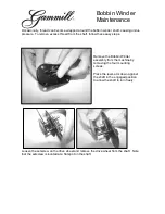
Bobbin Winder
Brand: Gammill Pages: 3

hobbylock 4764
Brand: Pfaff Pages: 36

INNOVATECH P550Y
Brand: Bartell Pages: 20

Memory Craft 7000
Brand: Janome Pages: 94

MA4
Brand: CIMLINE Pages: 60

AMS-210EN-1306
Brand: JUKI Pages: 4

APW-895/IP-420
Brand: JUKI Pages: 124

Proteus 26
Brand: Pacific Pages: 17
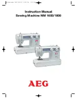
NM 1600
Brand: AEG Pages: 20


