background image

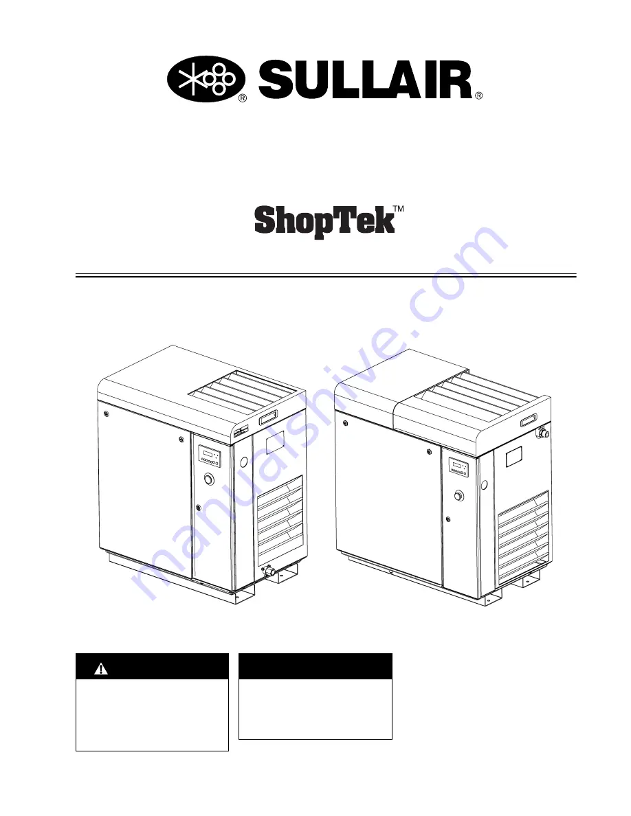
ST4, ST5, ST7, ST11, ST15

4 – 15 kW (5 – 20 hp)

Three-phase 60 Hz

PART NUMBER:

88292018-236 R00

The information in this manual is current as of its 

publication date and applies to compressor models 

indicated on this cover with 

serial number

:

37216100224

and all subsequent serial numbers until next revision of 

this manual or release of a replacement manual.

USER MANUAL

Publication date: 03/31/2017

Copyright © 2017 Sullair, LLC. All rights reserved.

 WARRANTY NOTICE

Failure to follow the instructions 
and procedures in this manual, 
or misuse of this equipment, will 

void

 its warranty.

Subject to EAR, ECCN EAR99 and related export control restrictions.

 SAFETY WARNING

Users are required to read the 
entire User Manual before han-
dling or using the product. Keep 
the User Manual in a safe place 
for future reference.

Summary of Contents for ShopTek ST11

Page 1: ... of this manual or release of a replacement manual USER MANUAL Publication date 03 31 2017 Copyright 2017 Sullair LLC All rights reserved WARRANTY NOTICE Failure to follow the instructions and procedures in this manual or misuse of this equipment will void its warranty Subject to EAR ECCN EAR99 and related export control restrictions SAFETY WARNING Users are required to read the entire User Manual...

Page 2: ...includes training on the function and installation of Sullair service parts troubleshooting common faults and malfunctions and actual equipment operation These seminars are recommended for maintenance contractor maintenance and service personnel For detailed course outlines schedule and cost information contact Sullair Training Department 1 888 SULLAIR or 219 879 5451 ext 5623 www sullair com trai...

Page 3: ... 12 Safety warnings 6 Section 2 Description 9 2 1 Introduction 9 2 2 Compressor component description 9 2 3 Compressor cooling and lubrication system functional description 14 2 4 Compressor discharge system functional description 14 2 5 Control system functional description 15 2 6 Air inlet system functional description 18 2 7 Controller keypad 19 2 8 LCD display 19 2 9 LED lights 20 Section 3 Sp...

Page 4: ... direction check 38 Section 5 Operation 39 5 1 Routine operation 39 Section 6 Maintenance 41 6 1 General 41 6 2 Maintenance after initial 50 hours of operation 41 6 3 Maintenance schedule 41 6 3 1 Every 2000 hours of operation or six months whichever occurs first 41 6 3 2 Every 2000 hours of operation or one year whichever occurs first 41 6 3 3 Every 4000 hours of operation or one year whichever o...

Page 5: ...Subject to EAR ECCN EAR99 and related export control restrictions iii 6 9 Replacement and alignment of belt pulleys 50 6 9 1 Instructions for installing a pulley 50 6 9 2 Instructions for removing a pulley 50 6 10 Hose maintenance 50 6 11 Tank mount package maintenance 50 6 12 Troubleshooting 51 ...

Page 6: ...Table of Contents ShopTek ST4 ST5 ST7 ST11 ST15 Three phase 60 Hz User Manual Notes 88292018 236 R00 iv Subject to EAR ECCN EAR99 and related export control restrictions ...

Page 7: ...n are applicable to most compressors and the concepts behind these state ments are generally applicable to all compressors 1 2 Personal protective equipment A Prior to installing or operating the compressor own ers employers and users should become familiar with and comply with all applicable OSHA regula tions and or any applicable Federal State and Local codes standards and regulations relative t...

Page 8: ...cal material or on any external surfaces of the air compressor Wipe down using an aqueous industrial cleaner or steam clean as required If necessary remove acoustical mate rial clean all surfaces and then replace acoustical material Any acoustical material with a protective covering that has been torn or punctured should be replaced immediately to prevent accumulation of liq uids or fluid film wit...

Page 9: ...t and DO NOT discharge air from these systems into unventilated or other confined areas C Operate the compressor only in open or adequately ventilated areas D Locate the compressor or provide a remote inlet so that it is not likely to ingest exhaust fumes or other toxic noxious or corrosive fumes or substances E Coolants and lubricants used in this compressor are typical of the industry Care shoul...

Page 10: ...ided with a lifting bail then lift by the bail provided If no bail is provided then lift by sling Compressors to be air lifted by helicopter must not be supported by the lifting bail but by slings instead In any event lift and or handle only in full compliance with OSHA standards 29 CFR 1910 sub part N and or any applicable Federal State and Local codes standards and regulations B Inspect points o...

Page 11: ...ng the work except when motion is necessary during setup adjustment or trouble shooting A The established procedures for the application of energy control shall cover the following elements and actions and shall be initiated only by Authorized Per sons and done in the following sequence 1 Review the equipment or machine to be locked and tagged out 2 Alert operator and supervisor of which machine i...

Page 12: ...eed motor drives These cautions that apply to VSD operation WARNING Ground the unit following the instructions in this manual Ungrounded units may cause electric shock and or fire The variable speed drive has a large capacitive leakage current during opera tion which can cause enclosure parts to be above ground potential Proper grounding as described in this manual is required Failure to observe t...

Page 13: ...ION Do not touch any components on the circuit boards Static voltage discharge may damage the components CAUTION Install the variable speed drive in a well venti lated room that is not subject to temperature extremes high humidity or condensation and avoid locations that are directly exposed to sun light or have high concentrations of dust corro sive gas explosive gas inflammable gas grinding flui...

Page 14: ...1 Safety ShopTek ST4 ST5 ST7 ST11 ST15 Three phase 60 Hz User Manual Notes 88292018 236 R00 8 Subject to EAR ECCN EAR99 and related export control restrictions ...

Page 15: ...diator fluid cooler and air aftercooler This hot air is then vented out of the top of the enclosure Fluid is injected into the compressor and mixes directly with the air as the rotors turn which compresses the air The fluid flow has three basic functions As a coolant it controls the air temperature rise normally associated with the heat of compres sion Seals the clearance paths between the rotors ...

Page 16: ...10 Subject to EAR ECCN EAR99 and related export control restrictions Figure 2 1 Main components ST4 ST5 ST7 1 Fluid filter 7 E stop button 2 Fluid cooler 8 Controller 3 Air inlet filter 9 Main motor 4 Separator tube 10 Compressor unit 5 Fluid fill sight glass 11 Cooler fan motor 6 Fluid fill ...

Page 17: ...ct to EAR ECCN EAR99 and related export control restrictions 11 Figure 2 2 Main components ST11 ST15 1 Fluid filter 7 E stop button 2 Aftercooler fluid cooler 8 Controller 3 Air inlet filter 9 Main motor 4 Separator tube 10 Compressor unit 5 Fluid fill sight glass 11 Cooler fan motor 6 Fluid fill ...

Page 18: ...r Manual 88292018 236 R00 12 Subject to EAR ECCN EAR99 and related export control restrictions Figure 2 3 Cooling lubrication and discharge system ST4 ST5 ST7 1 Separator tube 5 Separator element 2 Cooler 6 Air 3 Fluid filter 7 Air fluid mix 4 Compressor unit 8 Fluid ...

Page 19: ...scription 88292018 236 R00 Subject to EAR ECCN EAR99 and related export control restrictions 13 Figure 2 4 Cooling lubrication and discharge system ST11 ST15 1 Separator tube 5 Separator element 2 Cooler 6 Air 3 Fluid filter 7 Air fluid mix 4 Compressor unit 8 Fluid ...

Page 20: ...ra tor tube The separator tube has three basic functions It acts as a primary fluid separator Serves as the compressor fluid sump Houses the final fluid separator The compressed air fluid mixture enters the separator tube and flows through an internal baffle system that changes the flow s direction and velocity which causes most of the fluid to fall to the bottom of the separator tube A small amou...

Page 21: ...llowing compressed air to flow into the service line From this point on the Controller continuously monitors the line air pressure The solenoid valve remains closed in this mode As long as the compressor is running at 127 psig 8 8 bar or lower the inlet valve is fully open Unload mode greater than 127 psig 8 8 bar When there is no or only a small demand the service line pressure will rise The cont...

Page 22: ...al 88292018 236 R00 16 Subject to EAR ECCN EAR99 and related export control restrictions Figure 2 5 Control system ST4 ST5 ST7 1 Air outlet 5 Separator tube 2 Unload solenoid valve 6 Pressure transducer 3 Air inlet 7 Controller 4 Minimum pressure check valve 8 Check valve ...

Page 23: ...escription 88292018 236 R00 Subject to EAR ECCN EAR99 and related export control restrictions 17 Figure 2 6 Control system ST11 ST15 1 Air outlet 5 Separator tube 2 Unload solenoid valve 6 Pressure transducer 3 Air inlet 7 Controller 4 Minimum pressure check valve ...

Page 24: ...as a check valve to prevent reverse rotation when the compressor is shut down Figure 2 7 Air inlet system ST4 ST5 ST7 1 Air inlet filter 4 Clamp 2 Clamp 5 Compressor unit 3 Inlet tube WARNING The Plastic Pipe Institute recommends against the use of thermoplastic pipe to transport com pressed air or other compressed gases in exposed above ground locations e g in exposed plant piping 1 Sullube shoul...

Page 25: ... internal temperature operat ing mode and load status The modes are MANUAL STOP AUTOMATIC or FAULT Refer to Figure 2 10 If a machine fault occurs the red fault indicator will light up and the display will indi cate that a fault has occurred The lower line will display the cause of the fault Refer to service instructions to correct the cause Press and hold the Return Reset pad to reset the controll...

Page 26: ...the display will return to normal view in about one minute If the Start Stop or Return Reset buttons are pressed the display also returns to normal view If any of these occur the setting will not be altered If there are any warnings or recommended service instructions these will be periodically displayed on the normal view The list of displays may be navigated from either direc tion by using the U...

Page 27: ... bar 125 psi 12 bar 175 psi Relief valve setpoint 14 8 bar 215 psi Voltage frequency 208 230 460V 60 Hz or 575V 60 Hz Air end type Single stage oil injected rotary screw Configuration Belt driven Motor type TEFC IP55 Motor rating 3 7 kW 5 hp 5 5 kW 7 5 hp 7 5 kW 10 hp 11 kW 15 hp 15 kW 20 hp Motor nominal speed 3520 rpm Starting mode Full voltage Service factor 1 25 Ambient temperature Between 4 a...

Page 28: ...agrams P I and wiring diagrams WDs for your compressor are included in the packet of printed documentation included with your compressor PDFs of these drawings are included on the documenta tion CD included with our compressor CAUTION Do not mix different types of lubricants Mixing lubricants can cause malfunctions or compres sor damage and will void the compressor s war ranty CAUTION Contaminatio...

Page 29: ...ShopTek ST4 ST5 ST7 ST11 ST15 Three phase 60 Hz User Manual 3 Specifications Notes 88292018 236 R00 Subject to EAR ECCN EAR99 and related export control restrictions 23 ...

Page 30: ...3 Specifications ShopTek ST4 ST5 ST7 ST11 ST15 Three phase 60 Hz User Manual 88292018 236 R00 24 Subject to EAR ECCN EAR99 and related export control restrictions 3 6 ID ST4 ST5 ST7 88290017 299 R01 ...

Page 31: ...6 HAND HOLD A7 CONTAINMENT PAN DRAIN A8 E STOP A9 CONTROLLER 1 ALLOW 4 00 FEET 1 25 METERS MINIMUM CLEARANCE AROUND MACHINE FOR ACCESS AND FREE CIRCULATION OF AIR 2 A FOUNDATION OR MOUNTING PACKAGE CAPABLE OF SUPPORTING THE WEIGHT OF THE PACKAGE AND RIGID ENOUGH TO MAINTAIN THE COMPRESSOR FRAME LEVEL IS REQUIRED 3 ALL DIMENSIONS ARE 50 12 7MM 4 RECOMMENDED INCOMING CUSTOMER POWER SUPPLY IS SHOWN O...

Page 32: ...3 Specifications ShopTek ST4 ST5 ST7 ST11 ST15 Three phase 60 Hz User Manual 88292018 236 R00 26 Subject to EAR ECCN EAR99 and related export control restrictions 3 7 ID ST11 ST15 88290017 300 R01 ...

Page 33: ... HAND HOLD A7 CONTAINMENT PAN DRAIN A8 E STOP A9 CONTROLLER 1 ALLOW 4 00 FEET 1 25 METERS MINIMUM CLEARANCE AROUND MACHINE FOR ACCESS AND FREE CIRCULATION OF AIR 2 A FOUNDATION OR MOUNTING PACKAGE CAPABLE OF SUPPORTING THE WEIGHT OF THE PACKAGE AND RIGID ENOUGH TO MAINTAIN THE COMPRESSOR FRAME LEVEL IS REQUIRED 3 ALL DIMENSIONS ARE 50 12 7MM 4 RECOMMENDED INCOMING CUSTOMER POWER SUPPLY IS SHOWN ON...

Page 34: ...ations ShopTek ST4 ST5 ST7 ST11 ST15 Three phase 60 Hz User Manual 88292018 236 R00 28 Subject to EAR ECCN EAR99 and related export control restrictions 3 8 Piping and instrumentation ST4 ST5 ST7 88290016 646 R04 ...

Page 35: ...P WS708 7 88290014 222 1 GLASS SIGHT M33 8 1 VALVE THERMAL 185 DEG F ES11 9 88290015 765 1 COOLER OIL WS4 5 7 10 88290014 484 1 ELEMENT LUBE FLTR 5 20 HP 11 1 SAFE VALVE 12 02250046 338 1 VALVE MINIMUM PRESSURE GROUP E08E 13 88290014 514 1 SENSOR PRESSURE 250PSI 4 20MA 14 88290015 548 1 GAUGE CTL AIR PRESS WS11 15 15 1 TANK 16 88290002 432 1 VALVE BALLDN6 Q11MP 25P SSAIP 17 88290015 219 1 VALVE SO...

Page 36: ...cations ShopTek ST4 ST5 ST7 ST11 ST15 Three phase 60 Hz User Manual 88292018 236 R00 30 Subject to EAR ECCN EAR99 and related export control restrictions 3 9 Piping and instrumentation ST11 ST15 88290015 826 R03 ...

Page 37: ...014 222 1 GLASS SIGHT M33 8 02250078 204 1 VALVE THERMAL 185 DEG F ES11 9 88290014 225 1 COOLER COMB AC OC WS11 WS15 10 88290014 484 1 ELEMENT LUBE FLTR 5 20 HP 11 1 SAFE VALVE 12 02250046 338 1 VALVE MINIMUM PRESSURE GROUP E08E 13 88290014 514 1 SENSOR PRESSURE 250PSI 4 20MA 14 88290015 548 1 GAUGE CTL AIR PRESS WS11 15 15 1 TANK 16 88290002 432 1 VALVE BALLDN6 Q11MP 25P SSAIP 17 88290015 219 1 V...

Page 38: ...3 Specifications ShopTek ST4 ST5 ST7 ST11 ST15 Three phase 60 Hz User Manual Notes 88292018 236 R00 32 Subject to EAR ECCN EAR99 and related export control restrictions ...

Page 39: ...d permit easy access to all compressor compo nents Walls and ceilings with soft or porous surfaces absorb sound and reduce ambient noise levels Hard surfaces reflect noise and have little effect on ambient noise levels 4 1 1 Outdoor installation sheltered ShopTek packages are equipped with TEFC motors and have water tight controls that are IP54 rated and are suit able for sheltered outdoor install...

Page 40: ...t of the area to prevent its recirculation back into the compressor s cooling system Ducting or some other means must be used to ensure that hot exhaust air is vented away from the compressor if the compressor s housing has minimal overhead clearance Table 4 1 Ventilation requirements Model Ventilation air required cfm m3 hr ST4 612 1040 ST5 612 1040 ST7 612 1040 ST11 1471 2500 ST15 1471 2500 NOTE...

Page 41: ...T7 ST11 ST15 Three phase 60 Hz User Manual 4 Installation 88292018 236 R00 Subject to EAR ECCN EAR99 and related export control restrictions 35 Figure 4 2 Shipping studs ST11 ST15 1 Belt guard 3 Shipping studs 2 2 Nut 2 ...

Page 42: ...egs line filter s and isolation valves see Fig ure 4 3 on page 36 Figure 4 3 Typical service air piping 1 Sullair compressor 5 Standard gate valve 2 Sullair dryer 6 By pass gate valve 3 Shut off gate valve A1 Condensate drain 4 Sullair filter A2 Air outlets NOTE Systems using both reciprocating and rotary screw compressors must isolate the two types from each other through the use of a common rece...

Page 43: ...t glass should be completely full Add fluid if the level is visible or if no fluid is visible at all 4 6 Electrical preparation Interior electrical wiring is installed at the factory Required customer wiring should be done by a qualified electrician in compliance with OSHA National Electric Code and or any applicable local electrical codes apply ing to isolation switches fused disconnects etc Sull...

Page 44: ...tart the motor When looking at the motor from the compressor unit the shaft should turn clockwise for ST4 ST5 and ST7 and counterclockwise for ST11 and ST15 If reverse rotation occurs disconnect the power to the starter and exchange any two of the three power input leads then re check rotation A Direction of Rotation decal is located on the motor drive housing to show proper motor compressor rotat...

Page 45: ...ection 6 12 Troubleshooting on page 51 under Excessive compressor fluid consumption for a probable cause and corrective action After a routine start observe the controller display for the proper indications for this phase of operation After the compressor has warmed up check all compressor oper ation indications to ensure that it is running properly WARNING High pressure hazard Removing caps plugs...

Page 46: ...5 Operation ShopTek ST4 ST5 ST7 ST11 ST15 Three phase 60 Hz User Manual Notes 88292018 236 R00 40 Subject to EAR ECCN EAR99 and related export control restrictions ...

Page 47: ...6 1 and Figure 6 2 6 3 Maintenance schedule You should perform maintenance according to the follow ing schedule 6 3 1 Every 2000 hours of operation or six months whichever occurs first Clean the return line strainer Refer to Figure 6 1 and Figure 6 2 Pull fluid sample from fluid sample valve for analysis Refer to Figure 6 3 6 3 2 Every 2000 hours of operation or one year whichever occurs first Rep...

Page 48: ... conditions or whichever occurs first Every 2000 hours a display on the controller indicates the need for replacement Every fluid change 6 5 1 Fluid filter replacement Refer to Figure 6 3 1 Use a strap wrench to remove the fluid filter and gasket 2 Dispose of the old filter according to applica ble federal state and local regulations 3 Clean gasket seating surface 4 Apply a light film of fluid to ...

Page 49: ...re 6 5 Air filter maintenance should be performed every 2000 hours or sooner if nec essary 6 6 1 Air filter element replacement 1 Remove enclosure panels to gain access to filter 2 Loosen hose clamp and remove filter 3 Install new filter and tighten hose clamp Figure 6 4 Air filter assembly ST4 ST5 ST7 1 Air filter element 2 Clamp 3 Hose Figure 6 5 Air filter assembly ST11 ST15 1 Air filter elemen...

Page 50: ...e the separator elements every 1 year or 4000 hours whichever occurs first The separator elements must be replaced Do not attempt to clean and reinstall the separator elements Figure 6 6 Separator element assembly ST4 ST5 ST7 1 Cover 3 Separator element 2 Cover gasket 4 Separator tube Figure 6 7 Separator element assembly ST11 ST15 1 Cover 3 Separator element 2 Cover gasket 4 Separator tube ...

Page 51: ...f increasing belt tension Refer to Figure 6 10 and Figure 6 11 Belt tension must be re adjusted to 2 hours after a new set of belts are fitted This will ensure that the belts have completed their initial stretch Subsequent to this belt tension needs to be checked and adjusted if necessary every 2000 hours for the duration of the belt life There are two recommended methods for checking the belt ten...

Page 52: ...mplete revolution and measure the belts again recording the results 5 Repeat step 4 for a total of 3 measurements 6 Average the three measurements to obtain the true belt tension 7 Repeat for remaining belts 8 Compare the results to the belt tension spec ification in Table 6 1 and adjust if necessary 6 8 3 Belt tension adjustment Refer to Figure 6 10 and Figure 6 11 Adjust the belt tension accordi...

Page 53: ...2018 236 R00 Subject to EAR ECCN EAR99 and related export control restrictions 47 Figure 6 10 Belt tension adjustment ST4 ST5 ST7 1 Belt guard 5 Comp unit mounting plate bolts 4 2 Belt tension adjustment screw 6 Comp unit pulley 3 Locking nut 7 Belts 4 Jacking nut 8 Motor pulley ...

Page 54: ...92018 236 R00 48 Subject to EAR ECCN EAR99 and related export control restrictions Figure 6 11 Belt tension adjustment ST11 ST15 1 Belt guard 5 Comp unit mounting plate bolts 4 2 Belt tension adjustment screw 6 Comp unit pulley 3 Locking nut 7 Belts 4 Jacking nut 8 Motor pulley ...

Page 55: ...ncy Hz Force N Force N ST4 series ST410 5 60 80 70 233 180 ST410 5 50 82 72 232 178 ST5 series ST510 7 5 60 78 68 214 165 ST510 7 5 50 84 74 215 165 ST7 series ST709 10 60 87 76 250 192 ST712 10 60 81 71 242 186 ST708 10 50 90 79 237 182 ST713 10 50 85 79 230 191 ST11 series ST1109 15 60 85 75 245 189 ST1112 15 60 85 74 254 195 ST1108 15 50 92 81 248 191 ST1113 15 50 89 78 255 196 ST15 series ST15...

Page 56: ...ect alignment 6 9 1 Instructions for installing a pulley 1 Clean all surfaces of shaft pulley and taper lock bushing 2 Fit taper lock bushing inside pulley 3 Spray oil or anti seize compound on the grub screw threads and gently screw in 4 Slide the pulley bushing assembly on to the shaft to the correct position aligning the key way 5 Tighten the grub screws in stages to the specification in Table ...

Page 57: ...volt age check power source or contact local power company High operating pressure Reset if fault persists check line pres sure and ensure that it does not exceed the compressor s maximum operating pressure Compressor shuts down under service load condi tions High Pressure Fault Compressor pressure setting incor rect Change setting in Controller Control line strainer clogged Clean or replace strai...

Page 58: ...trol system leak causing loss of pressure signals Check for leaks Inlet valve stuck open Remove the intake hose and check the inlet valve for proper operation Defective unload solenoid valve Check the valve for proper operation open when energized replace if nec essary Plugged obstructed control line strainer Clean or replace strainer Pressure sensor malfunction Check connection and sensor replace...

Page 59: ...Subject to EAR ECCN EAR99 and related export control restrictions ...

Page 60: ... subject to change without prior notice Subject to EAR ECCN EAR99 and related export control restrictions Sullair LLC 3700 East Michigan Boulevard Michigan City IN 46360 USA www sullair com 1 800 SULLAIR USA only 1 219 879 5451 non USA ...

Reviews: