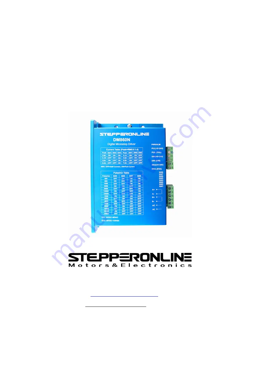
background image

User’s Manual

For

DM860N

Digital Microstep Drive

Version 1.1

Designed by STEPPERONLINE®

Manufactured by NC-THCH®

©2018 All Rights Reserved

#7 Zhongke Road, Jiangning, Nanjing, China
Tel: 086-25-8715-6578
Web site: www.omc-stepperonline.com
E-Mail: [email protected]

Attention: Please read this manual carefully before using the drive!

Summary of Contents for DM860N

Page 1: ...signed by STEPPERONLINE Manufactured by NC THCH 2018 All Rights Reserved 7 Zhongke Road Jiangning Nanjing China Tel 086 25 8715 6578 Web site www omc stepperonline com E Mail sales stepperonline com Attention Please read this manual carefully before using the drive ...

Page 2: ...ption 4 3 1 Control Signal Wirings Description 4 3 2 Motor Wirings Description 5 3 3 Input Signals Description 5 3 4 Timing Diagram of Control Signals 6 3 5 Wiring Requirements 7 4 DIP Switch Setting 7 4 1 Operating Current Setting 7 4 2 Standstill Current Setting 8 4 3 Microstep Resolution Setting 8 5 Power Supply Selection 8 5 1 Power Supply Precautions 8 5 2 Power Supply Recommend 9 6 Motor sel...

Page 3: ...till current can be set to half Can drive 4 6 and 8 wire two phase four phase stepper motors High speed optocoupler isolation signal input pulse response frequency up to 200 kHz Strong anti high frequency interference ability Easy to set output current Microstep accuracy 2 4 8 16 32 64 128 5 10 20 25 40 50 100 125 Overvoltage undervoltage overcurrent and phase to phase short circuit protection 1 3...

Page 4: ...put Voltage 24 80 100 110 contain the ripple VDC 18 60 75 80 contain the ripple VAC Control Signal Voltage 5 26 contain the ripple VDC Control Signal Current 7 10 16 mA Signal Pulse Frequency 0 200 KHZ Insulation Resistance 500 MΩ 2 2 Operating Environment and other Specifications Cooling Natural Cooling Operating Environment Environment Dustproof anti oil fog and corrosive gases Ambient Temperatu...

Page 5: ...reater than 2 5µs PUL voltage range is 5V 24V PUL PUL DIR 5 24V This signal can modify the motor direction In order to ensure the reliability of the motor the DIR signal should be established at least 5µs ahead of the PUL signal The initial running direction of the motor is related to the wiring sequence of the motor DIR voltage range is 5V 24V DIR DIR ENA 5 24V The ENA signal is used to enable di...

Page 6: ... the running direction of the motor once B 3 3 Input Signals Description DM860N has high speed optocoupler inside that allows reception of long line controller signal open collector signal and PNP type output signal In the harsh environment we recommend using a long line controller circuit to make the anti interference ability strong Taking the open collector and PNP type output as an example and ...

Page 7: ...deviations PUL DIR and ENA signals should observe some rules as following figure show Figure 4 Timing diagram of control signals Remark 1 t1 ENA signal must be ahead of DIR signal by at least 5µs Usually ENA and ENA should be suspended 2 t2 DIR signal must be ahead of PUL signal falling edge by 5µs to ensure correct direction 3 t3 Pulse width is not less than 2 5µs ...

Page 8: ...n the energized motor stops there is still a large current flowing through the coil Pulling out the motor line terminal will cause a huge instantaneous induced electromotive force to burn the driver 5 It is strictly forbidden to add tin to the wire lead and then connect the terminal Otherwise the terminal may be damaged due to the contact resistance becoming large and overheating 4 DIP Switch Sett...

Page 9: ...tep Pulses rev SW5 SW6 SW7 SW8 2 400 OFF ON ON ON 4 800 ON OFF ON ON 8 1600 OFF OFF ON ON 16 3200 ON ON OFF ON 32 6400 OFF ON OFF ON 64 12800 ON OFF OFF ON 128 25600 OFF OFF OFF ON 5 1000 ON ON ON OFF 10 2000 OFF ON ON OFF 20 4000 ON OFF ON OFF 25 5000 OFF OFF ON OFF 40 8000 ON ON OFF OFF 50 10000 OFF ON OFF OFF 100 20000 ON OFF OFF OFF 125 25000 OFF OFF OFF OFF 5 Power Supply Selection The driver...

Page 10: ...all inductance motor has a high speed performance but the current is large The DM860N can drive Nema 34 two phase and four phase hybrid stepper motors 6 1 Motor matching 1 Define the load torque the ratio of the working speed range 2 1 a 2 ro 2 1 a J D M i J C T tation load the of inertia of Moment J load the of on accelerati angular Maximum 1 a on accelerati angular screw or on wheel Transmissi 2...

Page 11: ...r 2 Output current setting For the same motor the larger the current setting value the larger the motor output torque but the heat generated by the motor and the driver is more serious when the current is large The calorific value is not only related to the current setting value but also to the motor motion form and the motor dwell time The following setting method uses the rated current value of ...

Page 12: ...ries resistor A It is not required This driver has been compatible with all signal voltages between 5V and 24V 3 Q After the driver is working for a long time the outer casing is hot is it normal A This is normal Under normal temperature the outer casing will not affect the performance below 70 C 4 Q After the wiring the power indicator light is on but the motor does not turn What is the reason A ...

Reviews: