RAM3
(
CMP30
)
Remote Station Microphone
The
RAM3
(
CMP30
) allows you to remotely control all functions of Standard Hori-
zon fixed mount VHF radios which include GX1600, GX1700, GX2000, GX2100,
GX2150, GX2200, GX5000S and GX5500S. The full dot matrix display and pro
-
grammable keys make operation simple and fast. Additional features include turning
the radio on/off and all DSC functions including Distress. The
RAM3
(
CMP30
) can
be extended up to 70 feet using the optional CT-100 (23 Foot) extension cable. The
RAM3
(
CMP30
)
is backed by an industry leading 3-year waterproof warranty.
WARNING: Do not connect or remove the CMP30 (RAM3) microphone while
the radio is powered on. This may result in equipment failure.
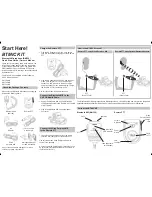
1. Connect the Extension Cable to the 8-pin connector on the transceivers rear
panel, then tighten the Cable Nut (Figure 1).
2. Referring to Figure 2, attach the supplied ferrite core as close as possible to the
MIC plug of the Routing Cable and External Speaker Connections, then snap its
two halves together. And then, wind some plastic tape around the ferrite core, to
prevent vibration from causing the two halves to split apart and fall off the wires.
3. Referring to Figure 3, make a 1.2” (30 mm) hole in the wall then insert the Exten
-
sion Cable into this hole. Connect the Gasket and Mount Base to the Extension
Cable Connector using the Nut.
4. Drill the four Screw holes (approx. 2 mm) on the wall then install the Mounting
Bracket to the wall using four screws.
5. Put the Rubber Cap on to the Nut.
6. The installation is now complete. Connect the
RAM3
(
CMP30
)
to the Extension
Cable Connector and tighten the Cable Nut.
RAM3
(
CMP30
)
I
nstallatIon
F
Igure
1
F
Igure
3
Copyright 2015
YAESU MUSEN CO., LTD.
All rights reserved.
No portion of this manual
may be reproduced
without the permission of
YAESU MUSEN CO., LTD.
I
ncluded
a
ccessorIes
and
replacement
part
numbers
1
. 23-Foot Routing Cable (S8101512)
2
. Rubber Cap (RA052520A)
3
. Mounting Bracket (RA052510) & Screws (U24312020 x 4 pcs)
4
. Microphone Hanger (RA0458800: Black or RA0436000: White) &
Screws (U40412220 x 2 pcs)
5
. Ferrite Core (L9190198)
F
Igure
2
Wall
Gasket
Mounting Bracket
Routing Cable
Cap
Nut
External Speaker Connections
Ferrite Core
As close as possible
Routing Cable or
CT-100 Extension Cable
Ferrite Core
Snap together
External Speaker
Connections
YAESU MUSEN CO., LTD.
Tennozu Parkside Building
2-5-8 Higashi-Shinagawa, Shinagawa-ku, Tokyo 140-0002 Japan
YAESU USA
6125 Phyllis Drive, Cypress, CA 90630, U.S.A.
YAESU UK
Unit 12, Sun Valley Business Park, Winnall Close
Winchester, Hampshire, SO23 0LB, U.K.
1506Y-GO
This device complies with part 15 of the FCC Rules. Operation is subject
to the following two conditions: (1) This device may not cause harmful
interference, and (2) this device must accept any interference including
received, interference that may cause undesired operation.
Owner’s Manual
The details of the installation and operation of the
RAM3
(
CMP30
) is included
in the owner’s manual of the compatible fixed mount radio, or it can be down
-
loaded at
www.standardhorizon.com. If you have any questions or comments,
please contact Standard Horizon Marine Product Support at 800/767-2450.
NOTE
Caution!
:
Before cutting the cable, it must be disconnected from the rear panel of
the transceiver.
The routing cable can be cut and spliced, however care needs to be taken
when reconnecting the wires to ensure water integrity.
After cutting you will notice there are the following wires:
Yellow, Green, Brown, Purple, Blue, Green, Red
, and Shield
The Red and Shield wires are wrapped in foil. Remove the foil, and sepa
-
rate the Red and Shield wires.
1
2
3
4
5
EAG36X104
o
ptIonal
a
ccessorIes
ct-100 23F
t
e
xtensIon
c
able
mls-310 10
watt
a
mplIFIed
s
peaker
mls-300 e
xternal
l
oud
s
peaker
s
pecIFIcatIons
Supply voltage
:
13.8 VDC (Supplied from the transceiver)
Current consumption
:
700 mA @VOL Max.
200 mA @AF Mute
Operating Temperature
: –4 °F to +140 °F (–20 °C to +60 °C)
MIC. Sensitivity
(Typical): 60 mVrms
@ 1 kHz Tone with 3 kHz Deviation
MIC. Impedance
:
2 k
AF output
:
300 mW @ 16
for 10 % THD
(Internal Speaker)
2 W @ 4
for 10 % THD
(External Speaker)
Display Size
:
1.8” x 0.9” (45 x 23 mm)
Display Resolution
:
132 x 64 dot
Case Size
:
2.6” x 5.5” x 1.2” (67 x 140 x 30 mm)
Weight
(Approx):
11.6 oz (330g)