Standard Communications TVM 450, Owner'S Manual
The Standard Communications TVM 450 Owner's Manual is available for free download from our website. This comprehensive manual enables you to fully understand and utilize the features of the TVM 450, ensuring a seamless user experience. Download your manual today at manualshive.com and make the most of your product.
Share
Download


Reviews:
No comments
Related manuals for TVM 450
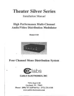
4101
Brand: Cable Electronics Pages: 8

DD-734
Brand: Datexx Pages: 1

DC-215WTLG
Brand: Datexx Pages: 1

DC-212
Brand: Datexx Pages: 1

Xpression fX Black Magic Motion
Brand: Oz inventions Pages: 61

MAC-HOME HD
Brand: IKUSI Pages: 24

EC-4004
Brand: Radio Shack Pages: 39

Time Master II
Brand: Calculated Industries Pages: 40

SDC-414N
Brand: Citizen Pages: 16

CT-500VII
Brand: Citizen Pages: 47

CCC-312
Brand: Citizen Pages: 48

CX-77BIII
Brand: Citizen Pages: 61

fx-55
Brand: Casio Pages: 2

FX-82LB
Brand: Casio Pages: 26

fx-350EX
Brand: Casio Pages: 24

FX 300
Brand: Casio Pages: 9

fx-570ES
Brand: Casio Pages: 75

ALGEBRA FX 2.0 Plus
Brand: Casio Pages: 54


