background image

PAGE 1

P52110_MXXXXX_Jan2020

PAGE 1

HELPFUL HINTS

+

   If  your spreader does not spread 

evenly, be sure “FRONT” on the GEAR-

BOX points to the front of the spread-

er. The impeller must turn clockwise 

when pushing forward.  Reversing  

the GEARBOX will cause the impeller 

to turn counter clockwise. Clean the 

impeller plate after each use. Fertilizer 

stuck on the impeller blades will cause 

uneven spreading.  

+

   Your  spreader is designed to be 

pushed at three miles per hour, which 

is a brisk walking speed. 

Clean and 

dry your spreader thoroughly after 

each use. 

 Coat all metal surfaces 

(pay special attention to the inside & 

outside of tubing - it’s easiest to do 

while assembling) with light oil, Fluid 

Film

®

 or silicon spray  to help prevent 

corrosion. Wash between the shut off 

plate and the bottom of the hopper. 

Do not use powdered materials.

+

   Gears are permanently lubricated at 

the factory.  

Do not open the gearbox 

or dirt may enter.

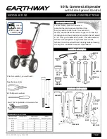
COMMERCIAL BROADCAST SPREADER

Model: 

2150 

SSC ASSEMBLY & OPERATION

ROCK SALT &  

POWDERED MATERIALS 

SHOULD NOT BE USED


in this spreader as it will damage 

gearbox and can void warranty.


USE ONLY 

GRANULAR MATERIALS

Summary of Contents for 2150

Page 1: ... which is a brisk walking speed Clean and dry your spreader thoroughly after each use Coat all metal surfaces pay special attention to the inside outside of tubing it s easiest to do while assembling with light oil Fluid Film or silicon spray to help prevent corrosion Wash between the shut off plate and the bottom of the hopper Do not use powdered materials Gears are permanently lubricated at the ...

Page 2: ...e holding the pinion shaft to engage with the COIN fully and press down to secure Next insert Cross Brace thru the Gearbox Brace as shown to the right FRONT Impeller Cross Brace GEARBOX ASSEMBLY Gearbox Brace Pinion Shaft Press turn Impeller to engage Coin securely Coin BOLT IDENTIFIER 1 1 2 1 2 2 1 4 2 3 4 31104 Qty 4 32100 Qty 2 33117 Qty 1 31100 Qty 4 31120 Qty 4 32103 Qty 8 31106 Qty 2 33108 Q...

Page 3: ...hen through FRAME brace Next into threaded connector in CROSS BRACE NOTE Numbers on frame brace must be facing toward gear box as shown Next into threaded connector in cross brace DO NOT TIGHTEN Install the FOOT into the FRAME and align the bolt holes in the FOOT and the FRAME a Phillips screwdriver or large nail is helpful to align the parts C Next insert 1 bolt through other end of FRAME BRACE a...

Page 4: ...el and through AXLE Bend with pliers to prevent pin from falling out 8 Install COAST WHEEL onto the AXLE fully then using outside cotter pin hole insert 1 cotter pin through AXLE not thru the wheel Bend with pliers to prevent pin from falling out TURN SPREADER UPRIGHT ON TO WHEELS NOW GO BACK AND TIGHTEN ALL NUTS AND BOLTS STARTING WITH FIRST STEP DO NOT OVER TIGHTEN 9 Insert 2 bolt through Gauge ...

Page 5: ...T BRACKET pull LEVER backward to insert CON TROL ROD through hole in PIVOT BRACKET Now install 1 4 20 regular nut on to CONTROL ROD Install HANDLE SHAFT to LOWER HANDLEs and PIVOT BRACKET assembly as shown Using 2 bolts and locknuts TIGHTEN BOLTS NUTS NOW ASSEMBLY 13 Install 1 1 4 20 Hex nut not a locknut on to control rod as shown Shut Off Plate Pivot Rod with extra bend Rotate Pivot Angle Attach...

Page 6: ...R MUST PLACE THE SHUT OFF PLATE IN THE FULL OPEN POSITION TO BE PROPERLY CALIBRATED Now tighten the nuts against the PIVOT BRACKET to prevent change in calibration 16 17 Tension on the flow control LEVER may be adjusted by tightening or loosening the tension nut on gauge and lever assembly Insert agitator into pinion shaft on inside of hopper NOTE the position of flat side of the agita tor in the ...

Page 7: ...0 12274 GRIP 2150 2170 7 5 LONG 30 70138 PNEUMATIC DRIVE WHEEL STUD 2150 S25 11 44251 PIVOT ROD 2150 2170 C22 C24 31 60333 New Floating GEAR BOX 2150 C22 12 60298 GAUGE LEVER ASSEMBLY 2150 C22 32 12148 AXLE BEARING 2130 2150 2170 S25 13 60175 UPPER HANDLE SQUARE W GRIP 33 12152 AXLE BUSHING 2130 2150 2170 S25 14 24500 AXLE COINED 34 33109 3 16 X 2 COTTER PIN ZINC 15 31100 1 4 20 X 1 1 2 HHMS ZINC ...

Page 8: ... outlined in 1 above B If your shut off is able to open fully as in step 1 but the Control Lever is not at 30 Loosen the top nut a few turns then loosen the lower nut so that it allows you to push the Control Lever to 30 Next tighten each nut so that they contact the pivot bracket without moving it Carefully tighten each nut fully so they do not loosen during use Recheck adjust as outlined in 1 ab...

Page 9: ... 9 LBS 28 16 4 9m 23 13 5 4 1m 26 16 4 9m 10 LBS 30 16 4 9m 25 13 5 4 1m 30 16 4 9m GRASS SEED LBS PER 1 000 FINE SPREAD SPREAD COARSE SPREAD SPREAD SQUARE FEET SETTING WIDTH FT METERS SETTING WIDTH FT METERS 2 LBS 11 8 5 2 6m 16 11 3 4m 3 LBS 16 8 5 2 6m 18 11 3 4m 4 LBS 18 8 5 2 6m 21 11 3 4m 5 LBS 20 8 5 2 6m 24 11 3 4m GRANULAR MATERIAL PARTICLE SIZES Fine Small Medium Large 1 5mm SAND 2mm 3mm...

Page 10: ...Y SIDE SPREAD CONTROL TECHNOLOGY for a Partial spread pattern and prevent material from being spread to the left side of the spreader Position the left wheel of your spreader 12 16 from the sidewalk flowerbed or driveway and spread as normal When you have completed this spreading pass open the EARTHWAY SIDE SPREAD CONTROL TECHNOLOGY by sliding the control lever from right to left for a FULL spread...

Reviews: