SpectraLink NetLink Wireless Telephone, Installation Manual
The SpectraLink NetLink Wireless Telephone is a cutting-edge communication device designed for seamless wireless communication. This compact and lightweight phone offers exceptional clarity and reliability. For convenient setup, make sure to download the free Installation Manual from our website for step-by-step instructions.
Share
Download


Reviews:
No comments
Related manuals for NetLink Wireless Telephone

SecPath V1000-A
Brand: H3C Pages: 69

Flight Stream 110/210
Brand: Garmin Pages: 46

SmartNode 4170
Brand: Patton electronics Pages: 52

EXCCGLA01
Brand: LOVATO ELECTRIC Pages: 22

WELLGATE 26 Series
Brand: WELLTECH Pages: 94

HP 3000
Brand: AVM Pages: 12

Tempus Air BW
Brand: Toro Pages: 40

011801
Brand: Popp Pages: 13

DEVG2020 DOT
Brand: NETGEAR Pages: 25

CG814WG
Brand: NETGEAR Pages: 2

MCC 3100
Brand: Nortel Pages: 134

Remote Office 9150
Brand: Nortel Pages: 570

CODA-4 8 Series
Brand: Hitron Pages: 150

FieldGate SWG50
Brand: Endress+Hauser Pages: 48

Connect L
Brand: HOOC Pages: 2

DA50N
Brand: Redlion Pages: 8

HomeConnect 3CRWE50194
Brand: 3Com Pages: 2
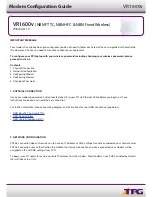
Archer VR1600v
Brand: TP-Link Pages: 5


