To review our Limited Warranty Statement & Return Policy for this or any SoundOff Signal product please visit our website at www.soundoffsignal.com and select the “Warranty & Returns”
link along the left column of our home page. If you have questions regarding this product please contact Technical Services, Monday - Friday, 8 am to 5 pm at 1.800.338.7337, press #4 to
skip the automated message. Questions or comments that do not require immediate attention may be emailed to [email protected].
1.800.338.7337. / www.soundoffsignal.com / Thank you for trusting us with your safety!
OPERATION:
For details on operation see page with ‘Flash
Patterns’ table on last page.
Please see separate sheet
for Technical Specifi cations
• Warning devices are strictly regulated and governed by Federal, State and Municipal ordinances.
These devices shall be used ONLY on approved vehicles. It is the sole responsibility of the user of these
devices to ensure compliance.
• DO NOT install this product or route any wires in the Air Bag Deployment Zone. Refer to your vehicle
Owner’s Manual for the location of any air bag deployment zones.
• DO NOT connect this device to a strobe power supply. This product is self-contained and does not
require an external power supply.
ENT2B3(x) 7.10
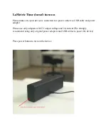
Important Information:
The INTERSECTOR LED Light is designed to
be mounted under the vehicle’s side mirrors
and provide a warning signal to the front
and sides. It can also be surface mounted.
INSTALLATION:
Loosely assemble Intersector Light, correct
wedge block and curve block (P=Passenger,
D=Driver’s side, Crown Vic and Dodge
Charger only) and position assembly below
side rear view mirror as shown at left.
Carefully remove light from stack without
changing position of wedge block. Mark and
drill pilot holes for #6 sheet metal screw.
Drill
3/8” hole in mirror shell if wire is to
be routed internally. If wire will be routed
external of the mirror shell this step can be
ignored.
Dismount mirror from door.
The following is particular to the Ford Crown
Vic but can be applied to other vehicles as
well:
After pilot holes for #6 sheet metal screws
are drilled, a
3/8” bit should be used to
drill hole in race way next to mirror power
race. A
3/8” hole should then be made
between the pilot holes and then angled
toward the race way as shown in Figures
2-6 (second page). It is important to avoid
drilling through the power cable as this will
damage the mirror.
Using #6 machine screw, washer and
square nut assemble light and appropriate
wedge block, curve block (if required)
and gasket. Route wire carefully through
3/8” hole and into door. Use appropriate
#6 sheet metal screws to attach light to
underside of mirror.
DO NOT OVERTIGHTEN
SCREWS AS THIS MAY DAMAGE THE
MIRROR OR LIGHT
. Mirror may now be
replaced on vehicle.
Attach supplied female connector and make
other appropriate wiring connections inside
of door.
WIRE HOOK-UP TABLE
WIRE COLOR:
(ALL WIRES 20ga)
CONNECT TO:
(FROM FLASHER ONLY)
RED
+10-16Vdc
WHITE
Pattern Select / Sync
BLACK
Ground (-)
GREEN
Cruise Mode (+10-
16Vdc)
!
WARNING
This product contains high intensity LED devices. To
prevent eye damage, DO NOT stare into the light
beam at close range.
Mirror Light
Shown with
optional cord
strain relief
Wedge Block
0°, 5° and 10°
Curved Surface
Adaptor (used on
Crown Vic and
Charger only)
Foam Gasket
RED
WHITE
BLACK
GREEN
D
B
C
A
D
B
C
A
RED
WHITE
BLACK
GREEN
FEMALE
CONNECTOR
MALE
CONNECTOR
FROM FLASHER
INTERSECTOR
LIGHT
ALL WIRES 22ga
IMPORTANT:
Power should only be
supplied through RED
WIRE of fl asher harness
and must be fused with
a 3A, user supplied,
in-line fuse. Failure to
install this fuse will create
a fi re hazard and will
damage the Intersector
Light. Connecting the
Intersector light to any
power source directly
WILL
permanently
damage the light and will
void warranty.
INTERSECTOR LED LIGHT
ENT2B3(x)