background image

INSTALLATION, OPERATION AND MAINTENANCE GUIDE

FOR SOUCY TRACK SYSTEMS:
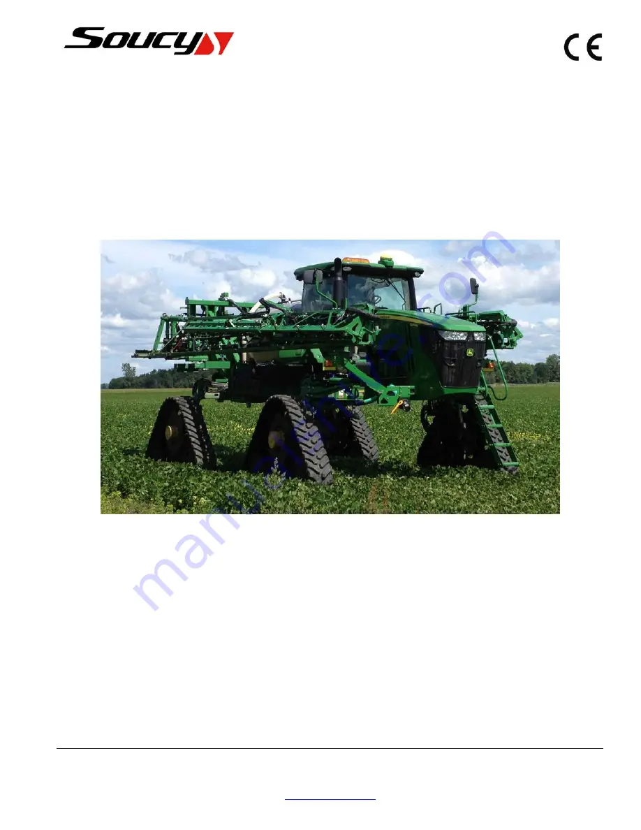
S-TECH 7016

installed on the following John Deere self-propelled sprayer models:

R4030 – R4038 – 4730 – 4830

A-8L0104-2-EN
Rev. B

May 2017

5450 St-Roch Street, P.O. Box 400 / Drummondville (Quebec) J2B 6W3 / CANADA

Toll free: 1 877 474-6665

Fax: 819 477-9423

www.soucy-track.com

Summary of Contents for S-TECH 7016

Page 1: ...EMS S TECH 7016 installed on the following John Deere self propelled sprayer models R4030 R4038 4730 4830 A 8L0104 2 EN Rev B May 2017 5450 St Roch Street P O Box 400 Drummondville Quebec J2B 6W3 CANA...

Page 2: ...Page Intentionally Left Blank 5450 St Roch Street P O Box 400 Drummondville Quebec J2B 6W3 CANADA Toll free 1 877 474 6665 Fax 819 477 9423 www soucy track com...

Page 3: ...ION 6 PART LIST AND INSTALLATION OF SYSTEM 17 6 1 PART LIST OF TRACK SYSTEM 17 6 2 FRONT COMPONENTS REMOVAL 34 6 3 BRACKET INSTALLATION 36 6 3 1 BRACKET INSTALLATION FOR JD R4030 36 6 3 2 BRACKET INST...

Page 4: ...10 1 SCOPE 71 10 2 COMMITMENT 71 10 3 WARRANTY PERIOD 71 10 4 EXCLUSION 72 10 5 LIMITATIONS 72 10 6 TERMS 73 SECTION 11 REPLACEMENT PROGRAM FOR RUBBER TRACKS 75 11 1 AGRICULTURAL TRACK 75 11 2 ELIGIB...

Page 5: ...TRACK SYSTEM SPECIFICATIONS Track Weight Corner Footprint S TECH 7016 Rear 16 in 406 mm 2500 lbs 1135 kg 1150 in 0 74 m NOTICE DRIVING ON ROADS WITH TRACKS CAN INCREASE TREAD WEAR UP TO 15 TIMES FASTE...

Page 6: ...DER IN EACH TRACK SYSTEM TO LUBRICATE THE TRACK AND WHEELS REDUCE SPEED AND LOAD ON CROWNED ROADS TO PREVENT UNEVEN TRACK WEAR CLEAN UP BUILD UPS OF MUD AND RESIDUE ON THE CHASSIS ON A REGULAR BASIS D...

Page 7: ...Rear View Measurements ITEM DESCRIPTION VALUE MM IN A CLEARANCE ON TRACK 1626 64 B OVERALL WIDTH 3658 144 C OVERALL HEIGHT ON TRACKS 4090 161 D OVERALL HEIGHT ON TRACKS AIRBAG DEFLATED 3990 157 E OVER...

Page 8: ...Page Intentionally Left Blank INSTALLATION OPERATION AND MAINTENANCE GUIDE 4...

Page 9: ...icant degradation NOTICE THIS GUIDE MAY BE REVISED BASED ON OPERATIONAL EXPERIENCE FEEDBACK FROM USERS AND DESIGN IMPROVEMENTS OF THE TRACK SYSTEM 2 2 HOW TO USE THIS GUIDE NOTICE THIS GUIDE REFLECTS...

Page 10: ...ure 2 1 Track System Main Assembly ITEM DESCRIPTION 1 ATTACHMENT 2 UNDERCARRIAGE 3 TENSIONER 4 MID ROLLERS 5 IDLERS 6 SPROCKET 7 RUBBER TRACK 6 7 4 3 5 2 1 INSTALLATION OPERATION AND MAINTENANCE GUIDE...

Page 11: ...bol The symbol above draws your attention to important instructions concerning your personal safety Read the accompanying message carefully to avoid personal injury or death Keep this manual in the ca...

Page 12: ...rack system Use jacks hoist or lift when manipulating heavy parts Make sure no one is in the danger zone of the vehicle while the engine is running or the vehicle is moving Read your vehicle owner s m...

Page 13: ...RE WARNING HEAVY PARTS CAN CAUSE INJURIES TWO PEOPLE ARE REQUIRED FOR ASSEMBLY AND REMOVAL OF THE SOUCY TRACK SYSTEM USE A JACK A FORKLIFT OR A HOIST TO HANDLE SYSTEM AND SUB ASSEMBLIES Check for poss...

Page 14: ...e any missing damaged or illegible sticker Soucy Track recommends placing the different stickers in the cabin in an area where they won t block the outside view Figure 3 3 SAMPLE INSTALLATION OPERATIO...

Page 15: ...INSTALLATION OPERATION AND MAINTENANCE GUIDE 11...

Page 16: ...Page Intentionally Left Blank INSTALLATION OPERATION AND MAINTENANCE GUIDE 12...

Page 17: ...e and track The frame serial number is located on the identification plate riveted on its side The track serial number is engraved on its inner surface DEALER PLEASE COMPLETE THE TRACK SYSTEM REGISTRA...

Page 18: ...Page Intentionally Left Blank INSTALLATION OPERATION AND MAINTENANCE GUIDE 14...

Page 19: ...or crane Torque wrench Bottle jack 18 in of stroke Jack stands 65 to 80 in M20 X 2 5 Tap 5 2 PREPARATION Make sure you have all the required parts and tools to do the job The parts should be clean and...

Page 20: ...ontact surfaces on vehicle axle housings track system attachments and frames This will prevent hardware loosening that can result in broken components and injuries Use anti seize compound with bolts s...

Page 21: ...SECTION 6 PART LIST AND INSTALLATION OF SYSTEM 6 1 PART LIST OF TRACK SYSTEM INSTALLATION OPERATION AND MAINTENANCE GUIDE 17...

Page 22: ...0 1 1 R4030 FRONT RIGHT BRACKET ASS Y 3 8031027 0920 1 1 R4030 FRONT LEFT BRACKET ASS Y 4 8031027 0800 1 1 R4030 REAR RIGHT BRACKET ASS Y 5 8031027 0930 1 1 R4030 REAR LEFT BRACKET ASS Y 6 8032007 015...

Page 23: ...TECH 7016 TRACK 2 8031032 0024 2 1 LEFT BRACKET ASS Y JD 4730 3 8031032 0025 2 1 RIGHT BRACKET ASS Y JD 4730 4 8032007 0150 1 1 SP 716 LEFT FRAME ASS Y 5 8032007 0160 1 1 SP 716 RIGHT FRAME ASS Y 6 80...

Page 24: ...Figure 6 3 PART LIST OF FRONT BRACKET WITH BRAKES FOR JOHN DEERE R4030 AND R4038 8031027 180 1 23 24 25 22 27 28 2 1 3 4 5 6 10 9 7 8 12 13 14 15 16 17 19 21 11 20 26 18 18A R4030 R4038 INSTALLATION...

Page 25: ...2 SIDE SHIM SMALL 2 15 8031027 0730 1 2 SIDE SHIM SMALL 3 16 8031027 0740 1 2 MAIN PLATE 17 8031027 0790 1 6 SHIM MAIN PLATE 18 8031027 0810 1 1 R4030 RIGHT PAINTED BRACKET 18A 8031027 0860 1 1 R4030...

Page 26: ...LS ONLY Figure 6 4 PART LIST OF REAR BRACKET FOR JOHN DEERE R4030 AND R4038 8031027 0800 1 16 16A 21 22 24 20 26 1 2 3 4 5 6 7 8 9 10 14 15 19 12 11 23 17 25 13 18 21 R4030 R4038 INSTALLATION OPERATIO...

Page 27: ...HIM SMALL 3 14 8031027 0740 1 2 MAIN PLATE 15 8031027 0790 1 6 SHIM MAIN PLATE 16 8031027 0810 1 1 R4030 RIGHT PAINTED BRACKET 16A 8031027 0860 1 1 R4030 LEFT PAINTED BRACKET 17 8031027 0840 1 2 SHIM...

Page 28: ...Figure 6 5 PART LIST OF REAR LEFT BRACKET WITH BRAKES FOR JOHN DEERE 4730 AND 4830 8031032 0024 2 4730 4830 7 22 11 23 16 18 17 20 14 15 19 10 13 12 9 8 6 5 4 3 2 1 24 22 18 21 19 18 20 INSTALLATION O...

Page 29: ...1 4 SHIM MAIN PLATE 12 8031032 0020 1 2 FRONT SHIM 2 13 8031032 0021 1 2 FRONT SHIM 1 14 8031032 0022 1 1 CALIPER PLATE 1 15 8031032 0023 1 1 CALIPER PLATE 2 16 8031032 0031 1 8 SIDE SHIM LONG 3 17 S...

Page 30: ...Y Figure 6 6 PART LIST OF REAR RIGHT BRACKET WITH BRAKES FOR JOHN DEERE 4730 AND 4830 8031032 0025 2 4730 4830 11 7 16 17 20 24 14 10 13 12 9 8 22 6 5 4 3 2 1 24 23 22 20 15 19 18 21 INSTALLATION OPER...

Page 31: ...9 1 4 SHIM MAIN PLATE 12 8031032 0020 1 2 FRONT SHIM 2 13 8031032 0021 1 2 FRONT SHIM 1 14 8031032 0022 1 1 CALIPER PLATE 1 15 8031032 0023 1 1 CALIPER PLATE 2 16 8031032 0031 1 8 SIDE SHIM LONG 3 17...

Page 32: ...Figure 6 7 PART LIST OF FRAME 8032007 0160 1 22 1A 7 11 17 16 4 23 24 5 4 3 1 15 9 8 6 2 12 14 13 10 20 19 21 18 22 INSTALLATION OPERATION AND MAINTENANCE GUIDE 28...

Page 33: ...XLE PLAIN 11 8032007 0330 1 1 ROCKER LINK AXLE THREADED 12 8032007 0320 1 1 ROCKER LINK AXLE SUPPORT 13 8032007 1070 1 1 ADJUSTMENT ROD 14 8032007 1050 1 1 TENSION LINK LOCKER 15 8032007 0230 1 2 BUSH...

Page 34: ...3 1 2 ITEM PART QTY DESCRIPTION 1 78033030 0040 1 2 28 PITCH 3IN WIDE HALF SPROCKET 2 S1111 16070 0F7 14 HEX BOLT CL10 9 ZnNi M16 2 0 X 70 DIN 931 3 S4186 M160Q 097 14 HEX NYLON NUT CL10 ZnNi M16 2 0...

Page 35: ...4730 4830 A B A 8033032 0060 1 JD 4730 SPROCKET ADAPTOR B 8033038 0001 1 JD 4830 SPROCKET ADAPTOR Figure 6 10 PART LIST OF SPROCKET ADAPTOR R4030 R4038 8033021 0060 1 JD R4030 SPROCKET ADAPTOR INSTALL...

Page 36: ...LE SHAFT ASS Y 4 8034011 0050 1 2 HUB CAP 5 8034011 0120 1 2 SP 716 IDLER WHEEL AND HUB ASS Y 6 B32011 XQ SKF 4 TAPERED ROLLER BEARING 55 X 90 X 23 7 S1131 06015 0D7 12 HEX BOLT CL8 8 ZnNi M6 1 0 X 15...

Page 37: ...TAPERED ROLLER BEARING 55 X 90 X 23 7 S1131 06015 0D7 12 HEX BOLT CL8 8 ZnNi M6 1 0 X 15 DIN 933 8 S4214 M0550 000 2 KM 11 LOCK NUT M55 X 2 9 S4531 M0550 000 2 MB11 LOCK WASHER DIA 55 MM 10 S6701 000...

Page 38: ...IS PROPERLY SECURED SUPPORTED TO PREVENT IT FROM ACCIDENTALLY FALLING DURING THE INSTALLATION OF THE TRACKS IF NOT PROPERLY SECURED SUPPORTED SERIOUS PHYSICAL INJURIES COULD OCCUR 1 Remove wheel moto...

Page 39: ...NNECTED 4 Use a M20x2 5 tap to remove dust and rust on rear knuckle caliper bracket holes 5 Loosen hydraulic hose manifold and remove manifold bracket A from knuckle NOTICE A GAP OF 1 5 INCHES BETWEEN...

Page 40: ...3 4 5 6 7 and 8 to fill the gap between the bracket and knuckle If possible use the same number of shims on each side of the knuckle 3 Torque bolts ITEM PART QTY 1 S1111_16090_0F7 6 2 S4515_M160G_0DC...

Page 41: ...4 Install rear bolts C with lock washers B through OEM hose manifold bracket A A C B INSTALLATION OPERATION AND MAINTENANCE GUIDE 37...

Page 42: ...hims 8 9 and 10 7 Install bolts 11 and washers 12 5 2 3 7 1 4 6 9 8 10 12 11 ITEM PART QTY 1 8031027_0740_1 2 2 8031027_0270_1 2 3 8031027_0280_1 2 4 8031027_1660_1 2 5 S1111_16055_0F7 6 6 8031027_079...

Page 43: ...8 Re install disc A and brake caliper B using OEM bolts and nuts A B INSTALLATION OPERATION AND MAINTENANCE GUIDE 39...

Page 44: ...the gap between the bracket and knuckle If possible use the same amount of shims on each side of the knuckle 3 Hand tight bolts 4730 4830 ITEM PART QTY 1 S1111_16090_0F7 2 2 S1111_16130_0F1 6 3 S4515...

Page 45: ...washers 8 and nuts 11 7 Torque bolts 7 then bolts 7A and 12 4730 4830 ITEM PART QTY 1 8031032_0018_2 2 2 8031032_0022_1 1 3 8031032_0023_1 1 4 8031032_0004_2 1 5 8031032_0021_1 2 6 8031032_0020_1 2 7...

Page 46: ...8 Re install disc A and brake caliper B using OEM bolts and nuts A B INSTALLATION OPERATION AND MAINTENANCE GUIDE 42...

Page 47: ...THE REAR AXLE OF THE SPRAYER 1 Install rear idler axle using U bolts 3 and nuts 1 Do not install axle shim 2 on the undercarriage of the front axle of the sprayer 1 3 2 ITEM PART QTY 1 S4186_M160Q_09...

Page 48: ...pivot axle fits in the right bracket 3 Install bolts 5 through pivot axle into the right bracket Torque bolts 4 Install locking devices 6 and safety plates 7 with bolts 8 ITEM PART QTY 1 8031027_0220...

Page 49: ...s are facing the adaptor 1 Assemble half sprockets 1 and sprocket adaptor 2 with bolts 3 and nuts 4 2 Install sprocket assembly on sprayer with OEM nuts install only 2 nuts then see next page for spro...

Page 50: ...both side 4 To modify the sprocket position regarding to the undercarriage change arrangement of the lateral shims 1 on the pivot axle 2 Note that adding shims on the outside of the frame will move th...

Page 51: ...and tension link locker 2 2 Loosen the tensioner by turning the adjustement rod 3 counter clockwise use a 21 mm wrench A 1 2 3 A ITEM PART QTY 1 S5351_08032_002 1 2 8032007_1050_1 1 3 8032007_1070_1 1...

Page 52: ...con Teflon base lubricant to the internal face of the track before installing the track this will ease installation of the track NOTE NOTE A Direction of rotation of track NOTE A INSTALLATION OPERATIO...

Page 53: ...4 Use a fork lift to position the track over the planetary 5 Push the lug row between wheel 6 Lower the track kit to seat the wheels on the track INSTALLATION OPERATION AND MAINTENANCE GUIDE 49...

Page 54: ...sprocket 8 Push the track with the fork lift until the track is centered with the sprocket 9 Turn the tensioner screw clockwise to tighten the track 10 Measure deflection by applying pressure on trac...

Page 55: ...MUST BE MEASURED IN THE FRONT PORTION OF THE TRACK AFTER HAVING MOVED THE MACHINE FORWARD 11 To lock tensioner insert wire lock pin 1 and tension link locker 2 2 1 A A INSTALLATION OPERATION AND MAINT...

Page 56: ...Page Intentionally Left Blank INSTALLATION OPERATION AND MAINTENANCE GUIDE 52...

Page 57: ...e for a short distance 1 km and then check the integrity of the system and track lug overheat Make sure no one is in the danger zone of the vehicle while the engine is running or the vehicle is moving...

Page 58: ...from the idler wheel hub at the front and the back of the undercarriage 1 Use a tape to measure the distance between the frames at their front and back 2 Tracks must be toe in between 1 8 and 3 8 inc...

Page 59: ...NOTICE TO AVOID FRONT WHEEL TOE MISADJUSTMENT DO NOT TURN THE STEERING FULL LOCK ON EITHER SIDE WHEN MOVING BACKWARD INSTALLATION OPERATION AND MAINTENANCE GUIDE 55...

Page 60: ...ension Soucy Track recommends the following method of measuring deflection Other methods can be used Drive the sprayer forward for 5 feet 1 5 m to release tension due to sprocket drive and stop withou...

Page 61: ...he tape on the side of the sprocket as shown 2 Place your thumb over a number on the tape without applying pressure 3 Let someone grab the track firmly on each side and push hard two or three times NO...

Page 62: ...check if the track tension is adequate proceed with next steps to apply a force as per Table A 5 Remove the tensioner locking pin and plate 6 Turn the tensioner screw clockwise to increase the tension...

Page 63: ...Force kg lb Deflection mm in Force kg lb S TECH 7016 19 3 4 68 150 19 3 4 68 150 NOTE The tolerance is 6mm in each case Those value are indicative Do not put too much tension on the tracks It is bett...

Page 64: ...ND ON IT FOR MORE THAN A FEW SECONDS IF THE TEMPERATURE IS HIGHER ON ONE SIDE BUT IT IS LOWER THAN 60 C 140 C AFTER 10 MIN ON THE ROAD THE SYSTEM CAN BE OPERATED ANYWAY CHECK OVERHEATING ON BOTH SIDES...

Page 65: ...LLED ON THE SIDE WHERE THE LUG OVERHEATS TRACK TENSION MIGHT HAVE TO BE LOOSE TO CREATE ENOUGH ROOM BETWEEN PIVOT AXLE AND HOUSING SOUCY RECOMMEND ADDING SHIM OF 1 16 AT A TIME 9 When the shim is inst...

Page 66: ...Page Intentionally Left Blank INSTALLATION OPERATION AND MAINTENANCE GUIDE 62...

Page 67: ...tenance requirements applicable to the track system Maintenance intervals can be adjusted according to factors such as driving habits and operating conditions Table 8 1 Regular Maintenance Schedule Fr...

Page 68: ...ording to type of operation to prevent accumulation or packing of debris This is especially important when the tractor is used in muddy conditions or in claylike soil Also avoid ice accumulation Opera...

Page 69: ...ing at temperatures greater than 35 C 95 F for extended periods If possible release tension of tracks Do not store track system in closed areas with electric devices that generate ozone such as motors...

Page 70: ...Page Intentionally Left Blank INSTALLATION OPERATION AND MAINTENANCE GUIDE 66...

Page 71: ...tem slowly for a short period The dirt acts as a lubricant and enhances the track conditioning process Conditioning may need to be done more than once if the system is used on the road for long distan...

Page 72: ...g transport weight and speed and adjusting ballast for even transport weight distribution front to back A TRACKED MACHINE BALLASTED FOR PROPER FIELD OPERATION IS USUALLY NOT BALLASTED CORRECTLY FOR RO...

Page 73: ...o track overheating and premature damage to rubber tracks wheels and other components To avoid this kind of inconvenience Soucy Track recommends adjusting your speed on long distance trips hot pavemen...

Page 74: ...Page Intentionally Left Blank INSTALLATION OPERATION AND MAINTENANCE GUIDE 70...

Page 75: ...harp and precise pictures clearly showing the problem may be required Soucy International Inc retains the right to replace a defective part product with an updated version These modifications will not...

Page 76: ...l failure of the tractor as well as damage caused by an accident or the spilling of chemicals on the track Damages seen as purely aesthetic that do not hinder the system performance or durability 10 5...

Page 77: ...DEFECTIVE PART BE RETURNED 6 Any repair done by an authorized agent of Soucy Track will be subject to a reimbursement of labour costs under the following conditions a Labour time allowed for repairs...

Page 78: ...Page Intentionally Left Blank INSTALLATION OPERATION AND MAINTENANCE GUIDE 74...

Page 79: ...ly the nature of failure or defect b The warranty only covers the tracks that have become unusable due to defects in material or manufacturing as recognized by Soucy in the evaluation of the failure o...

Page 80: ...determined 1 Method to measure the height of the tread a Place the rubber track into a position so that the tread is straight and flat b Use a straight edge and a tape measure Measure the height of t...

Page 81: ...99 376 417 513 563 650 739 10 9 283 302 391 439 552 613 753 827 954 1085 12 9 331 353 457 514 646 717 881 967 1117 1270 Bolt mm 6 8 10 12 14 Thread Coarse Fine Coarse Fine Coarse Fine Coarse Fine Coar...

Page 82: ...108 154 213 301 Bolt mm 12 14 16 18 20 Class Tightening Torque ft lb 10 9 60 80 114 157 222 NOTE Applicable to new lubricated new unlubricated and used lubricated bolts Torque indicated on drawing is...

Page 83: ...INSTALLATION OPERATION AND MAINTENANCE GUIDE 79...

Page 84: ...URS OF USAGE WERE THE OPERATOR MANUAL AND WARRANTY POLICY SUPPLIED AND EXPLAINED TO CLIENT CONTACT PERSON CLIENT NAME ADDRESS VEHICLE BRAND In order to prevent any transcription and or transmission er...

Reviews: