后面
B
7
防掉落钢绳安装螺丝孔
当将摄像机安装到天花板或墙上时,请使用附带的螺丝将防掉落钢绳固定到
此孔中。
8
U
接地端子(螺丝型)
若在连接中有噪音,请将此端子接地。
9
直流 12 V/交流 24 V(电源输入)端子(直流 12 V ±10%/交流 24 V
±10%)(SSC-DC693P/DC673P)
电源插座(交流 220-240 V,50 Hz)(SSC-DC698P/DC678P)
0
VIDEO OUT(复合视频信号输出)连接器(BNC 型)
qa
RS-485 终端(SSC-DC693P/DC698P)
使用此开关设定使用 RS-485 终端电阻或不使用。
qs
I/O 接口(SSC-DC693P/698P)
信 号
说 明
RS-485+
用于将来采用 RS-485 连接方式进行系统扩展
RS-485—
用于将来采用 RS-485 连接方式进行系统扩展
Alarm In
当 Alarm IN 端口连接外部信号设备时,警报由外部信号触
发。
当触发开启时,屏幕上显示警报指示,且 Alarm OUT 终端输
出 5V 信号。
*
GND
接地
Alarm Out
当触发 Alarm IN 时,Alarm OUT 终端将输出 5V 信号。
当选择彩色模式时,在此终端和 COM 之间输出 5V;当选择黑白
模式时,输出 0V。
*
COM
共用引脚
*
有关使用的详细说明,请参见附带的“菜单操作”手册。
(接背面)
U1/4”, 20 UNC
== 4.5 mm – 9 mm
(
ISO
标准)(用螺丝
固定)
中文
特点
SSC-DC693P/DC698P 与 SSC-DC673P/DC678P 彩色摄像机配备有 1/3 英寸传感
器 DynaView
+
技术并具有以下特点:
•
采用 DynaView
+
* 技术的宽动态范围
•
切换彩色/黑白模式的白天/夜间功能 (SSC-DC693P/DC698P)
•
自动白平衡寻迹和调节(ATW/ATW-PRO)
•
与直流控制信号控制型自动光圈镜头兼容
•
中央测光的逆光补偿
•
交流电源同步的线路锁定功能(50 Hz)SSC-DC698P/DC678P
* DynaView
+ TM
是 Sony 公司的注册商标。
使用须知
电源
•
SSC-DC693P/DC673P 必须使用 24 V 交流电源或 12 V 直流电源。SSC-DC693P/
DC673P 可自动检测电源。
-连接变压器时,请务必将各导线连接至适当的端子。错误的连接将导致
摄像机发生故障和(或)损坏。
-请将装置接地,否则交流电源线可能会产生不规则的电压,从而可能会
导致摄像机发生故障和(或)损坏。
•
SSC-DC698P/DC678P 必须使用 220-240 V(50 Hz) 交流电源。
操作
请小心不要溅水或溅洒其他液体在本机上,或使易燃物或金属物掉入机内。
若在异物进入机内的状态下使用本机,摄像机可能会发生故障或因此发生火
灾或触电。
操作与存放场所
请避免长时间将摄像机对准强光物体(如阳光、照明光)。请避免在以下场
所使用或存放本机。
•
极热或极冷(操作温度为-10℃~+50℃)的地方
•
潮湿或多尘处
•
遭到雨淋的地方
•
有剧烈振动的地方
•
靠近强电磁辐射发射机(如无线电或电视信号发射机)的地方
•
易受到荧光灯照射的地方
•
照明条件不稳定(闪烁等)的地方
保养
•
用气刷清除镜头或图像传感器表面的灰尘或污垢。
•
使用干燥、柔软的布擦拭机体。如果是顽垢,可先用布蘸少许中性洗涤剂
擦拭,然后用布擦干。
•
避免使用诸如稀释剂、酒精、苯和杀虫剂之类的挥发性溶剂进行清洁。否
则会破坏摄像机的表面涂层和(或)削弱其操作性能。
其他
•
当 BLC 菜单处于“OFF”以外的其他位置时,可能出现“猎振”。这是因为
摄像机“猎振”以设定最佳曝光等级而可能使图像变得忽明忽暗。遇此情
况时,请将 BLC 菜单设定于“OFF”位置。
•
在近处的红外线条件下,聚焦可能不如在可见光条件下清晰。
•
因镜头涂层的原因,在近处的红外线条件下摄像机可能无法发挥其最佳性
能。
有关在摄像机使用过程中出现的任何问题,请与您的 Sony 维修代理联系。
部件的位置和功能
顶部/前面/右侧
A
1
镜头接口
用于安装适当的 CS 型接口镜头。
2
焦距调节螺丝
使用此螺丝调节焦距(透镜平面与成像面之间的距离)。
3
镜头插口(4 针插座)
为自动光圈镜头(未附带)提供电源和控制信号。
4
三脚架螺丝孔
摄像机的顶部和底部都有用于安装三脚架的螺丝
孔。使用
1/4" UNC-20
螺丝将三脚架安装到摄像
机上。三脚架必须放置在平坦的表面上,并用手
拧紧。
5
MENU/ENTER 键
用于菜单操作。按此键显示菜单或确认设定。
有关使用的详细说明,请参阅附带的“菜单操作”手册。
6
X
/
x
/
C
/
c
键
使用这些键进行菜单操作。
X
和
x
键用于将光标上移和下移;
C
和
c
键用于
改变设定。
有关使用的详细说明,请参阅附带的“菜单操作”手册。
小心
只能使用长度为
4.5 mm – 9 mm
的安装螺丝。使用其它螺丝可能会造成
不当安装,并可能损坏摄像机内部零件。
1
6
4
2
3
5
A
4-124-764-
24
(1)
2008 Sony Corporation
Printed in China
http://www.sony.net/
Color Video Camera
彩色摄像机
Operating Instructions
Before operating the unit, please read this manual thoroughly
and retain it for future reference.
使用手册
使用本机前,请仔细阅读本使用手册并妥善保存以备日后参考。
SSC-DC693P/DC698P
SSC-DC673P/DC678P
English
Features
The SSC-DC693P/DC698P and SSC-DC673P/DC678P color video camera
is equipped with a 1/3 inch image sensor DynaView
+
technology and also
has the following features:
• Wide dynamic range using DynaView
+
*
technology
• Day/Night function allowing color/monochrome mode switching
(SSC-DC693P/DC698P)
• Automatic white balance tracking and adjustment (ATW/ATW-PRO)
• DC controlled auto-iris lens capability
• Backlight compensation through center measurement
• Line lock function for synchronizing through AC power source
(SSC-DC698P/DC678P: 50 Hz)
*
DynaView
+
TM
is a registered trademark of Sony Corporation.
Notes on Use
Power supply
• The SSC-DC693P/DC673P operates on either AC 24 V or DC 12 V
power. The SSC-DC693P/DC673P automatically detects the power.
– When connecting the transformer, be sure to connect each lead to the
appropriate terminal. Wrong connection may cause malfunction and/or
damage to the video camera.
– Ground the unit or an irregular voltage may be generated in the AC
power cord and may cause malfunction and/or damage to the video
camera.
• The SSC-DC698P/DC678P must always be operated with an AC 220 -
240 V (50 Hz) power supply.
Handling
Be careful not to spill water or other liquids on the unit, or allow combustible
or metallic objects to fall inside the body. If used with a foreign object inside,
the camera is liable to fail, or be a cause of fire or electric shock.
Operation and storage locations
Avoid aiming the camera at very bright objects such as the sun or electric
lights for an extended period. Avoid operating or storing the unit in the
following locations.
• Extremely hot or cold places (operating temperature –10 °C to + 50 °C
(14 °F to 122 °F))
• Damp or dusty places
• Where it is exposed to rain
• Where it is subject to strong vibration
• Close to generators of powerful electromagnetic radiation such as radio or
TV transmitters.
• Where it is subject to fluorescent light reflections
• Where it is subject to unstable (flickering, etc.) lighting conditions.
Care of the unit
• Remove dust or dirt on the surface of the lens or Image Sensor with a
blower.
• Use a dry, soft cloth to clean the body. If it is very dirty, use a cloth
dampened with a small quantity of neutral detergent, then wipe dry.
• Avoid using volatile solvents such as thinners, alcohol, benzene, and
insecticides. They may damage the surface finish and/or impair the
operation of the camera.
Other
• When the BLC menu is set to an option other than OFF, “hunting” may
occur, that is, the image may get darker and lighter as the camera “hunts”
for the optimum exposure level. If hunting occurs, set the BLC menu to
OFF.
• The focus may be less sharp under near infrared light than under visible
light.
• The best camera performance may not be obtained under near infrared
light due to the lens coating.
In the event of any problems with the operation of the camera, contact your
Sony dealer.
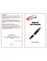
Location and Function of Part
Top/Front/Right Side
A
1
Lens mount
Use to mount an appropriate CS-mount lens.
2
Focal length adjustment screw
Use this screw to adjust the focal length (the distance between the lens
mounting plane and the image plane).
3
Lens connector (4-pin socket)
Supplies power and control signals to an auto-iris lens (not supplied).
4
Tripod screws
The screw holes for attaching the tripod are
located on both the top and bottom of the camera.
Use a 1/4" UNC-20 screw to attach a tripod to the
camera. The tripod must be set up on a flat
surface and tightened firmly by hand.
5
MENU/ENTER button
Use for menu operation. Press this button to display the menu or confirm
the settings.
For details of the use, see the supplied “Menu Operations” manual.
6
X
/
x
/
C
/
c
buttons
Use these buttons for menu operation. The
X
and
x
buttons move the
cursor upward and downward. The
C
and
c
buttons change the setting.
For details of the use, see the supplied “Menu Operations” manual.
CAUTION
Use the mounting screw whose length is 4.5 mm – 9 mm only. Use of
other screws may cause improper mounting and damage parts inside
the camera.
WARNING
To reduce a risk of fire or electric shock, do not
expose this product to rain or moisture.
To avoid electrical shock, do not open the
cabinet. Refer servicing to qualified personnel
only.
The apparatus shall not be exposed to dripping or splashing and no
objects filled with liquid, such as vases, shall be placed on the apparatus.
WARNING (SSC-DC678P/SSC-DC698P only)
The mains plug must be used to disconnect mains power. Please
ensure that the socket outlet is installed near the equipment and shall
be easily accessible.
ATTENTION
The electromagnetic fields at specific frequencies may influence the
picture of this unit.
CAUTION
This installation should be made by a qualified service person and
should conform to all local codes.
CAUTION
The nameplate is located on the bottom.
U1/4”, 20 UNC
== 4.5 mm – 9 mm
(ISO standard) (with
the screws fastened)
(continued on the reverse side)
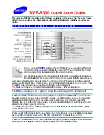
Rear
B
7
Fall-prevention wire rope mounting screw hole
When installing the camera to a ceiling or wall, secure the supplied fall-
prevention wire rope to this hole using the supplied screw.
8
U
Ground terminal (screw type)
If there are noises in the connections, connect this terminal to the ground.
9
DC 12 V/AC 24 V (power input) terminal (DC 12 V ±10% /AC 24 V
±10%) (SSC-DC693P/DC673P)
Power inlet (AC 220 - 240 V, 50 Hz) (SSC-DC698P/DC678P)
q;
VIDEO OUT (composite video signal output) connector (BNC type)
qa
RS-485 TERM SSC-DC693P/DC698P
Use this selector to set the camera with RS-485 terminal ON or OFF.
qs
I/O port (SSC-DC693P/DC698P)
Signal
Description
RS-485 +
for future system expansion using an RS-485 connection
RS-485 –
for future system expansion using an RS-485 connection
Alarm In
When Alarm IN port connects the external signal
equipment, the alarm is triggered by external signal.
When trigger on, alarm indicator is shown on the screen
and Alarm OUT terminal outputs a 5V signal.*
GND
connect with ground
Alarm Out
When Alarm IN is triggered, Alarm OUT terminal outputs a
5V signal.
5V is output between this terminal and COM when the color
mode is selected; 0V is output when the B&W mode is
selected.*
COM
common to pins
* For details of the use, see the supplied “Menu Operations” manual.
警告
为减少火灾或电击危险,请勿让本产品受到雨淋或
受潮。
为了避免触电,切勿打开机壳。只能请专业维修人
员进行维修。
设备不要受到滴水或水溅,不要将盛满液体的花瓶等物品放在设备上。
警告(仅限
SSC-DC698P/DC678P
)
必须使用电源插头断开电源连接。请确保电源插座安装在设备旁,并要
便于插拔。
声明
此为
A
级产品,在生活环境中,该产品可能会造成无线电干扰。
在这种情况下,可能需要用户对其干扰采取切实可行的措施。
一旦发生干扰,请联络附近的授权
Sony
维修机构。
本设备不应在住宅区使用。
注意
特定频率的电磁场可能会干扰本装置的图像。
小心
此项安装应由专业服务人员进行,并遵照所有本地法规。
小心
标牌在底部。