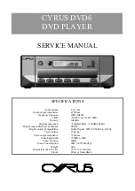
background image

SERVICE MANUAL

Model Name Using Similar Mechanism New

CD Mechanism Type

CDM-3325ER

Optical Pick-up Type

DAX-25E

US Model

Canadian Model

D-EJ100/EJ106CK

AEP Model

D-EJ100/EJ101

UK Model

D-EJ101

E Model

D-EJ100/EJ101/EJ101CK

Australian Model

D-EJ100/EJ106CK

SPECIFICATIONS

System

Compact disc digital audio system

Laser diode properties

Material: GaAlAs
Wavelength: £f = 780 nm
Emission duration: Continuous
Laser output: Less than 44.6 

µ

W (This output is the value

measured at a distance of 200 mm from the objective lens
surface on the optical pick-up block with 7 mm aperture.)

Power requirements

• Two size AA (LR6) batteries: 1.5 V DC x 2
• AC power adaptor (DC IN 4.5 V jack):
  100 - 240 V, 50/60 Hz (AEP, UK, EE, E18, Saudi Arabia, Thai)
  120 V, 60 Hz (US, Canadian, C&SA, Mexican)
  240 V, 50 Hz (Australian)

Dimensions (w/h/d) (without projecting parts and controls)

Approx. 135.8 x 22.8 x 135.8 mm (5 

3

8

 x 

29

32

 x 5 

3

8

 in.)

Approx. 135.8 x 23.5 x 135.8 mm (5 

3

8

 x 

15

16

 x 5 

3

8

 in.)*

*Psyc model

Mass (excluding accessories)

Approx. 180 g (6.4 oz)
Approx. 188 g (6.7 oz)*
*Psyc model

Operating temperature

5

°

C - 35

°

C (41

°

F - 95

°

F)

Design and specifications are subject to change without notice.

Supplied Accessories

D-EJ100/EJ101/EJ101CK/EJ106CK

Ver 1.2  2004. 04

Sony Corporation

Parsonal Audio Company

Published by Sony Engineering Corporation

9-961-981-03

2004D02-1

© 2004.04

PORTABLE CD PLAYER

Photo : D-EJ100

AC power adaptor (1)

  a

*

1

a     a

*

1

Headphones/earphones (1)

  a

*

1

a

Headphones/earphones


a

*

2

a

with  remote control (1)

Car connecting pack (1)

a

Car battery cord (1)

a

Rotary commander (1)

a

Velcro tapes for the CD

a

player (2)

Velcro tape for the rotary

a

commander (1)

Active speaker system (1)

*1 Not supplied with US and Canadian model
*2 Supplied with US and Canadian model
*3 “Operating Instructions for the car kit” is enclosed.

For the models supplied with the remote control

Use only the supplied remote control.  You cannot operate
this CD player with the remote control supplied with other
CD players.

D-EJ101CK/EJ106CK*

3

D-EJ101

D-EJ100

Summary of Contents for CD Walkman D-EJ100

Page 1: ... 135 8 x 23 5 x 135 8 mm 5 3 8 x 15 16 x 5 3 8 in Psyc model Mass excluding accessories Approx 180 g 6 4 oz Approx 188 g 6 7 oz Psyc model Operating temperature 5 C 35 C 41 F 95 F Design and specifications are subject to change without notice Supplied Accessories D EJ100 EJ101 EJ101CK EJ106CK Ver 1 2 2004 04 Sony Corporation Parsonal Audio Company Published by Sony Engineering Corporation 9 961 98...

Page 2: ...EJ101CK EJ106CK UNLEADED SOLDER Boards requiring use of unleaded solder are printed with the lead free mark LF indicating the solder contains no lead Caution Some printed circuit boards may not come printed with the lead free mark due to their particular size LEAD FREE MARK Unleaded solder has the following characteristics Unleaded solder melts at a temperature about 40 C higher than ordinary sold...

Page 3: ...utput IC601 yg pin When checking FOK remove the lead wire to disc motor RF signal P to P value 0 4 to 0 8Vp p SECTION 1 SERVICING NOTES Laser Diode Checking Methods During normal operation of the equipment emission of the laser diode is prohibited unless the upper panel is closed while turning ON the S809 push switch type The following two checking methods for the laser diode are operable Method E...

Page 4: ...ASSY CABINET LOWER ASSY z The equipment can be removed using the following procedure Cabinet lower ASSY MD ASSY Motor ASSY Sled M902 Optical pick up DAX 25E Turn table motor ASSY spindle M901 Main board Set Upper lid ASSY Cabinet upper ASSY 4 tow screws upper lid assy cabinet upper assy cabinet lower assy 5 claw 7 CN802 3 five screws 1 6 2 5 claw 5 claw ...

Page 5: ...5 D EJ100 EJ101 EJ101CK EJ106CK 3 2 MD ASSY CDM 3325ER MAIN BOARD 1 CN501 2 CN401 3 CN402 6 MAIN board MD assy CDM 3325ER 4 5 HOW TO SET THE HARNESS IN ASSEMBLING CN402 harness CN401 ...

Page 6: ...MOTOR ASSY SLED M902 OPTICAL PICK UP DAX 25E TURN TABLE MOTOR ASSY SPINDLE M901 6 2 4 9 5 motor assy sled M902 1 three screws B1 7x4 chassis 8 three screws B1 7x4 q turn table motor assy spindle M901 7 optical pick up DAX 25E 3 gear cover ...

Page 7: ... AC range and increase the vertical sensitivity of the oscilloscope for easy watch ing 5 Stop revolving of the disc motor by pressing the x button SECTION 4 ELECTRICAL ADJUSTMENTS The CD section adjustments are done automatically in this set Precautions for Check 1 Perform check in the order given 2 Use YEDS 18 disc Part No 3 702 101 01 unless otherwise indicated 3 Power supply voltage requirement...

Page 8: ...2 L401 L402 V BAT VCC2_2 0V VCC1_2 2V VCPU_1 5V VCC2 VCC SEM SEO VCC0 STNG LG VIN BATM1 BATM2 DCIN_S VBAT VCC1 VCPU 2 0V CHGMNT 24 66 VMMNT 61 DCIN 62 REGB X601 16 934MHz DVDDIO VCHK AVDD2 2 25V DVDDV 1 5V RDACO LDACO LOUT ROUT LIN RIN MUTE BEEP 20 PWRSW 5 VCC IC301 HEADPHONE AMP IC403 2 2 POWER CONTROL VCPU_2 0V EJ100 US CND E18 EJ101 EJ101CK EJ106CK model RFI A VCC1_2 2V B E FO3 RO3 FO2 RO2 FO1 ...

Page 9: ... R859 R858 R849 R854 R401 C810 C623 D405 C440 FB408 FB101 FB301 FB201 FB304 TP101 TP301 TP201 R438 D403 D802 D306 D408 C425 D302 D301 D101 D410 D201 D303 D803 TP813 TP815 TP821 TP820 TP818 TP816 TP817 TP812 TP814 TP810 TP808 TP807 TP806 TP804 TP805 TP809 TP811 TP803 TP802 TP801 TP819 C627 C412 TP409 TP414 TP413 TP402 L601TP602 TP603 TP608 TP614 TP607 TP613 TP601 13 1 24 12 1 TP407 BP801 40 21 61 4...

Page 10: ... CN601 R864 FB402 R863 L405 C428 L406 L605 L403 L404 L411 L409 L401 L402 L407 D402 Q407 Q402 Q403 1 15 OPTICAL PICK UP BLOCK DAX 25E R413 R412 C415 R411 R416 C427 C441 R427 R434 C445 R436 R444 R439 R457 R421 R314 R872 C808 R816 R871 S809 OPEN C318 FB302 J302 2 2 L305 FB401 L301 R322 EJ100 US CND E18 EJ101 EXCEPT TH EJ101CK EJ106CK EJ100 AUS LCD801 KEY MATRIX 2 3 4 5 6 7 8 9 A 1 B C D E F G PRINTED...

Page 11: ...D2 D3 A0 A1 A2 A3 A4 A5 A6 A7 A8 A9 A0 A1 A2 A3 D0 D1 D2 D3 A4 A5 A6 A7 A8 A9 XRAS XRAS XCAS XCAS XWE XWE OPEN HOLD RMKEY A10 A10 OPGSW OPSTB F T T F CLK4M J XBUSY FOK GFS D2 D3 A4 A5 A6 A7 A8 XCAS A0 A1 A2 A3 D0 D1 XRAS XWE SRW AMUTE BEEP IC601 BU9354CKV IC603 AVSS2 RLINO RLINI RDACO VCDACO LDACO LLINI LLINO AVDD2 2 25V MUTE DVDDIO 2 0V XIN XOUT DVSSIO DVDD 1 5V SCOR XRST POFF DVSSIO SCLK SRW SDI...

Page 12: ... SEG10 SEG11 SEG12 SEG13 SEG14 KEY 1 KEY 2 SCK SRW SDTO SDTI POWERLT SCOR RESET XWAKEUP XBUSY FOK CLK4M J GFS FG PGM SEL PGM SEL PGM SCK PGM SCK PGM SDTI PGM SDTI PGM SDTO PGM SDTO RESET2 RESET2 CLK4M J CLK4M J VOL VOL AMUTE XRST POFF OPSTB OPGSW CHGMNT DCINMNT SEG1 SEG2 SEG3 SEG4 SEG5 SEG6 SEG7 SEG8 SEG9 HOLD OPEN RMKEY VOL VOL BEEP KEY 1 KEY 2 COM COM COM SEG SEG SEG SEG SEG SEG SEG SEG SEG SEG ...

Page 13: ... 2SC4081T106R DEFFERENTIAL 47k 0 22 220k 47k 220 6 3V 22 10V 0 0 MA2YD2300LS0 1SS355TE 17 RB160M 30TR 1SS355TE 17 1SS355TE 17 2SB1132 T100 Q SWITCH 2SC4154TP 1F SWITCH 1 1 RSB6 8STE61 1 UDZSTE 175 1B PWM BUS 1 BUS 3 VIN VCC1 VCC2 VCC3 VCPU D GND AU GND A GND COMP BATMNT VCC4 GND 2 BUS 2 SYNC D AU GND BUS 5 POWERLT RESET SDTO SCK XWAKEUP FG XRST CHGMNT DCINMNT CPOL FIN FIN TIN TIN SIN SIN F T F T I...

Page 14: ...W BST OUT VCC ADDA ADDB 21 22 PW A ALC ALC IC601 BU9354CKV 1 100 AVDD1 2 0V 2 LD 3 PD 4 VMON 5 VCHK 6 E 7 F 8 B 9 A 10 AVSS1 11 BIAS 12 N C 13 RFI 14 PKC 15 BTC 16 RFGO 17 DETI 18 ASYI 19 ASYO 20 MON1 22 ADPFO 23 ADPFI 24 FCO 25 PCO 75 FDOP 74 FDON 73 CLVOP 72 CLVON 71 CLKDRV 70 GFS 69 EXPLCK 68 TEST_S 67 EFM YFLG 66 C2FX 65 FOK_O 64 63 62 61 60 59 58 DOCKO DOUTAO LRCKO DOUTAI LRCKI 57 TDO TEST DE...

Page 15: ...SPGND2 VG SSW VCC3 VIN DSW POWERGND USW VCC0 17 VCC1 18 VCC2 20 VCC FIN3 RIN3 FIN2 RIN2 FIN1 RIN1 VM1 0GND FO1 PGND1 VM12 RO1 FO2 PGND2 RO2 VM23 44 FO3 43 PGND3 42 RO3 41 VM3 76 WI PRE DRIVE LOGIC VG VCC VG SLOPE SIGNAL 77 VI 78 UI 79 COM 80 CSL2 XRST 37 WAKEUP 38 CLOXK 39 DATA 40 LATCH RESET_O SYNC PREGND EI SOFT SLOW EO PMG VCPUNF VCC2NF STNG SEP SEM SEO GSW INPUT SELECT CHARGE CONTROLLER LEVEL ...

Page 16: ... A D converter 21 AD_SEL I Destination setting terminal 22 AD_CHGMNT I Charging monitor input 23 AD_KEY_2 I Set s button detection input 24 AD_BATTMNT I Battery voltage monitor input 25 WP AD_KEY1 I Set s button detection input 26 WP AD_RMKEY I Remocon s button detection input 27 AD_DCINMNT I DC IN voltage monitoring input 28 WP XOPEN I OPEN switch status detection input 29 TUPWR_O O Not used OPEN...

Page 17: ...nous signal input 72 FG_I I FG signal input 73 PGMSEL_0 SC_SEL_0 O PGM select signal output 74 AMUTE_O O Mute ON OFF signal output 75 RESET_TU_O O Not used OPEN 76 XREST_O O System reset output 77 POFF_O O Power off signal output to BU9354CKV 78 XOPSTBY_O O Pick up s power supply ON OFF control signal output 79 OPGSW_O O RF IC s gain control signal output 80 C2POEN_O O Not used Fixd to L ...

Page 18: ...EP AUS E18 EE 7 3 261 284 21 BUTTON SOUND BLACK EJ101 E18 C SA 7 3 261 292 01 BUTTON SOUND PSYC WHITE EJ100 CND EJ101 AEP UK EE 9 3 261 229 01 BUTTON STOP SILVER EJ101 TH EJ101CK EJ106CK 9 3 261 229 11 BUTTON STOP BLUE EJ100 US EJ101 TH 9 3 261 283 01 BUTTON STOP SILVER EJ100 CND AEP AUS EE E18 EA EJ101 E18 C SA 9 3 261 283 11 BUTTON STOP BLUE EJ100 CND AEP AUS E18 EE 9 3 261 283 21 BUTTON STOP BL...

Page 19: ...EJ100 US EJ101CK EJ106CK 58 3 261 277 01 LEVER DETECTION EJ100 CND AEP AUS EE E18 EA EJ101 59 3 254 070 01 SCREW BLUE WHITE 59 3 254 070 11 SCREW SILVER BLACK 60 3 261 255 01 SPRING L 61 3 261 256 01 SPRING R 62 X 2021 366 1 CABINET UPPER SUB ASSY G EJ101 AEP UK EE 62 X 3384 381 1 CABINET UPPER SUB ASSY S SILVER EJ100 CND AEP AUS EE E18 EA EJ101 E18 C SA 62 X 3384 385 1 CABINET UPPER SUB ASSY L BL...

Page 20: ... 268 01 GEAR B 0107 X 3380 950 1 OPTICAL PICK UP DAX 25E RP ASSY 108 3 221 475 01 SHAFT STANDARD 109 3 222 298 01 RACK 110 3 222 299 01 SPRING RACK RETAINER 111 3 348 998 31 SCREW M1 4X2 5 TAPPING PAN M901 A 3180 965 A MOTOR ASSY TURN TABLE SPINDLE M902 A 3180 966 A MOTOR ASSY SLED including GEAR Les composants identifiés par une marque 0 sont critiques pour la sécurité Ne les remplacer que par un...

Page 21: ...22 1 162 968 11 CERAMIC CHIP 0 0047uF 10 50V C423 1 162 968 11 CERAMIC CHIP 0 0047uF 10 50V C425 1 104 852 11 TANTAL CHIP 22uF 20 10V C426 1 126 369 11 ELECT 220uF 20 6 3V C427 1 162 970 11 CERAMIC CHIP 0 01uF 10 25V C428 1 107 686 11 TANTAL CHIP 4 7uF 20 16V C429 1 164 156 11 CERAMIC CHIP 0 1uF 25V C432 1 124 434 00 ELECT 220uF 20 4V C433 1 115 156 11 CERAMIC CHIP 1uF 10V C434 1 124 589 11 ELECT ...

Page 22: ...11 FERRITE 0uH EJ100 US CND E18 EJ101 EXCEPT TH EJ101CK EJ106CK FB304 1 216 295 91 SHORT CHIP 0 FB401 1 216 864 11 METAL CHIP 0 5 1 10W FB402 1 216 864 11 METAL CHIP 0 5 1 10W FB403 1 216 295 91 SHORT CHIP 0 FB404 1 216 864 11 METAL CHIP 0 5 1 10W FB405 1 216 864 11 METAL CHIP 0 5 1 10W FB406 1 216 864 11 METAL CHIP 0 5 1 10W FB408 1 216 864 11 METAL CHIP 0 5 1 10W IC IC301 8 759 681 65 IC TA2120F...

Page 23: ...P 1M 5 1 10W R801 1 216 295 91 SHORT CHIP 0 R802 1 216 845 11 METAL CHIP 100K 5 1 10W R803 1 216 837 11 METAL CHIP 22K 5 1 10W R804 1 216 864 11 METAL CHIP 0 5 1 10W EXCEPT AEP UK EE R805 1 216 821 11 METAL CHIP 1K 5 1 10W R807 1 414 760 21 FERRITE 0uH R808 1 216 845 11 METAL CHIP 100K 5 1 10W R809 1 216 845 11 METAL CHIP 100K 5 1 10W R810 1 414 760 21 FERRITE 0uH R811 1 216 849 11 METAL CHIP 220K...

Page 24: ...AL INSTRUCTION POLISH CZECH SLOVAKIAN EJ101 EE 2 055 400 11 MANUAL INSTRUCTION THAI EJ101 TH 3 249 845 11 MANUAL INSTRUCTION ENGLISH FRENCH SPANISH PORTUGUESE EJ101CK EJ106CK CND AUS Les composants identifiés par une marque 0 sont critiques pour la sécurité Ne les remplacer que par une piéce portant le numéro spécifié The components identified by mark 0 or dotted line with mark 0 are critical for ...

Page 25: ...25 D EJ100 EJ101 EJ101CK EJ106CK MEMO ...

Page 26: ...e Also clicking the version at the upper right on the revised page allows you to jump to the next revised page Ver Date Description of Revision 1 0 2004 01 New 1 1 2004 02 Addition of D EJ100 CND BLUE D EJ101 E18 and D EJ101CK E18 ENG 04003 1 2 2004 04 Addition of D EJ100 EA and D EJ101 AEP UK EE TH models ...

Reviews: