background image

SERVICE MANUAL

COPYRIGHT © 2010 Victor Company of Japan, Limited

No.YD125<Rev.001>

2010/1

BLU-RAY DISC & HDD RECORDER 

YD125<Rev.001>

2010

1SERVICE MANUAL

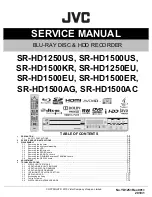
SR-HD1250US, SR-HD1500US, 

SR-HD1500KR, SR-HD1250EU, 

SR-HD1500EU, SR-HD1500ER, 

SR-HD1500AG, SR-HD1500AC

COPYRIGHT © 2010 Victor Company of Japan, Limited

TABLE OF CONTENTS

1

PRECAUTION  . . . . . . . . . . . . . . . . . . . . . . . . . . . . . . . . . . . . . . . . . . . . . . . . . . . . . . . . . . . . . . . . . . . . . . . . . . . . . . . . . . . . . . . . . . . . . .

1-3

1.1

SAFETY PRECAUTIONS. . . . . . . . . . . . . . . . . . . . . . . . . . . . . . . . . . . . . . . . . . . . . . . . . . . . . . . . . . . . . . . . . . . . . . . . . . . . . . .

1-3

2

SPECIFIC SERVICE INSTRUCTIONS. . . . . . . . . . . . . . . . . . . . . . . . . . . . . . . . . . . . . . . . . . . . . . . . . . . . . . . . . . . . . . . . . . . . . . . . . . . .

1-5

3

DISASSEMBLY  . . . . . . . . . . . . . . . . . . . . . . . . . . . . . . . . . . . . . . . . . . . . . . . . . . . . . . . . . . . . . . . . . . . . . . . . . . . . . . . . . . . . . . . . . . . . .

1-5

3.1

Removing the top cover . . . . . . . . . . . . . . . . . . . . . . . . . . . . . . . . . . . . . . . . . . . . . . . . . . . . . . . . . . . . . . . . . . . . . . . . . . . . . . . .

1-5

3.2

Removing the front panel assembly   . . . . . . . . . . . . . . . . . . . . . . . . . . . . . . . . . . . . . . . . . . . . . . . . . . . . . . . . . . . . . . . . . . . . . .

1-5

3.3

Removing the HDD. . . . . . . . . . . . . . . . . . . . . . . . . . . . . . . . . . . . . . . . . . . . . . . . . . . . . . . . . . . . . . . . . . . . . . . . . . . . . . . . . . . .

1-5

3.4

Removing the BD drive unit  . . . . . . . . . . . . . . . . . . . . . . . . . . . . . . . . . . . . . . . . . . . . . . . . . . . . . . . . . . . . . . . . . . . . . . . . . . . . .

1-5

3.5

Removing the REG/SD board. . . . . . . . . . . . . . . . . . . . . . . . . . . . . . . . . . . . . . . . . . . . . . . . . . . . . . . . . . . . . . . . . . . . . . . . . . . .

1-6

3.6

Removing the BE-DIGITAL board  . . . . . . . . . . . . . . . . . . . . . . . . . . . . . . . . . . . . . . . . . . . . . . . . . . . . . . . . . . . . . . . . . . . . . . . .

1-6

3.7

Removing the D-SUB/BNC board and TERMINAL board  . . . . . . . . . . . . . . . . . . . . . . . . . . . . . . . . . . . . . . . . . . . . . . . . . . . . . .

1-6

3.8

Removing the DISPLAY board . . . . . . . . . . . . . . . . . . . . . . . . . . . . . . . . . . . . . . . . . . . . . . . . . . . . . . . . . . . . . . . . . . . . . . . . . . .

1-6

4

ADJUSTMENT . . . . . . . . . . . . . . . . . . . . . . . . . . . . . . . . . . . . . . . . . . . . . . . . . . . . . . . . . . . . . . . . . . . . . . . . . . . . . . . . . . . . . . . . . . . . . .

1-7

5

TROUBLE SHOOTING  . . . . . . . . . . . . . . . . . . . . . . . . . . . . . . . . . . . . . . . . . . . . . . . . . . . . . . . . . . . . . . . . . . . . . . . . . . . . . . . . . . . . . . .

1-7

5.1

DISPLAYING TEST MODE  . . . . . . . . . . . . . . . . . . . . . . . . . . . . . . . . . . . . . . . . . . . . . . . . . . . . . . . . . . . . . . . . . . . . . . . . . . . . .

1-7

5.2

UPDATING MAIN UNIT FIRMWARE   . . . . . . . . . . . . . . . . . . . . . . . . . . . . . . . . . . . . . . . . . . . . . . . . . . . . . . . . . . . . . . . . . . . . .

1-7

5.3

UPDATING SYSCON FIRMWARE  . . . . . . . . . . . . . . . . . . . . . . . . . . . . . . . . . . . . . . . . . . . . . . . . . . . . . . . . . . . . . . . . . . . . . . .

1-8

5.4

UPDATING DRIVE FIRMWARE  . . . . . . . . . . . . . . . . . . . . . . . . . . . . . . . . . . . . . . . . . . . . . . . . . . . . . . . . . . . . . . . . . . . . . . . . .

1-8

5.5

INITIALIZING TO FACTORY SETTING   . . . . . . . . . . . . . . . . . . . . . . . . . . . . . . . . . . . . . . . . . . . . . . . . . . . . . . . . . . . . . . . . . . .

1-9

5.6

REPLACING HDD  . . . . . . . . . . . . . . . . . . . . . . . . . . . . . . . . . . . . . . . . . . . . . . . . . . . . . . . . . . . . . . . . . . . . . . . . . . . . . . . . . . .

1-10

5.7

Exchanging the fitting . . . . . . . . . . . . . . . . . . . . . . . . . . . . . . . . . . . . . . . . . . . . . . . . . . . . . . . . . . . . . . . . . . . . . . . . . . . . . . . . .

1-11

5.8

Taking out a disc. . . . . . . . . . . . . . . . . . . . . . . . . . . . . . . . . . . . . . . . . . . . . . . . . . . . . . . . . . . . . . . . . . . . . . . . . . . . . . . . . . . . .

1-11

5.9

DISPLAYING MAINTENANCE MODE . . . . . . . . . . . . . . . . . . . . . . . . . . . . . . . . . . . . . . . . . . . . . . . . . . . . . . . . . . . . . . . . . . . .

1-12

STOP

REV PLAY

PAUSE

FWD

OPEN/

CLOSE

STANDBY/ON

HDV/DV IN

REC

SD

REC

C

E

R

D

D

H

BD

ONE TOUCH

DUBBING

REC

MODE

RESET

INPUT

SELECT

HDD

MIDIA SELECT

BD/SD

Summary of Contents for SR-HD1250EU

Page 1: ...ng the HDD 1 5 3 4 Removing the BD drive unit 1 5 3 5 Removing the REG SD board 1 6 3 6 Removing the BE DIGITAL board 1 6 3 7 Removing the D SUB BNC board and TERMINAL board 1 6 3 8 Removing the DISPLAY board 1 6 4 ADJUSTMENT 1 7 5 TROUBLE SHOOTING 1 7 5 1 DISPLAYING TEST MODE 1 7 5 2 UPDATING MAIN UNIT FIRMWARE 1 7 5 3 UPDATING SYSCON FIRMWARE 1 8 5 4 UPDATING DRIVE FIRMWARE 1 8 5 5 INITIALIZING ...

Page 2: ...5 Ω DV 4 pin for HDV DV IN Remote Input 3 5 mm Jack Serial Command D SUB 9 PIN D SUB 9 PIN Component video output Y 1 0 Vp p 75 Ω CB CR PB PR 0 7 Vp p 75 Ω Corresponding to copy protection Digital audio output Optical PCM AAC Dolby Digital and DTS HDMI output 19 pin type A Deep Color x v Color Ver1 3 USB terminal USB2 0 SD memory card SD SDHC HDD Deck 250GB 500GB 250GB 500GB Recording compression ...

Page 3: ...ction will not loosen it Fig 1 1 2 10 Also check areas surrounding repaired locations 11 Products using cathode ray tubes CRTs In regard to such products the cathode ray tubes themselves the high volt age circuits and related circuits are specified for compli ance with recognized codes pertaining to X ray emission Consequently when servicing these products replace the cathode ray tubes and other p...

Page 4: ...rd plug prongs and externally ex posed accessible parts Use an AC voltmeter to measure across both terminals of load Z See Fig 1 1 9 and follow ing Fig 1 1 12 Fig 1 1 9 5 Grounding Class 1 model only Confirm specified or lower grounding impedance between earth pin in AC inlet and externally exposed accessible parts Video in Video out Audio in Audio out or Fixing screw etc Measuring Method Connect ...

Page 5: ...hen remove the front panel assembly Fig 2 Fig 3 3 3 Removing the HDD See Figure 4 Remove the top cover 1 Pull out the SATA cable and the HDD power cable con nected to the HDD 2 Remove the four screws C attaching the HDD bracket 3 HDD is removed from the HDD bracket Fig 4 3 4 Removing the BD drive unit See Figure 5 Remove the top cover 1 Pull out the SATA cable and the BD drive power cable con nect...

Page 6: ...ng the BE DIGITAL board 3 7 Removing the D SUB BNC board and TERMINAL board See Figure 9 and Figure 10 Remove the top cover 1 Pull out the socket wires from the connectors CN1501 and CN1502 on the BE DIGITAL board 2 Pull out the each wire from the connectors CN401 CN402 and CN403 on the D SUB BNC board Fig 9 3 Remove the five screws H and the two nuts attaching the each terminal from back of the m...

Page 7: ...isc Refer to JS NET for details of creating an update disc 1 Download the update file iso from SMIS in JS NET 2 Write the update file onto a CD R in image writing using writing software Be sure to write in Disc at Once Refer to the instructions of the writing software for image writing settings 5 2 2 Update Procedures 1 Place an update disc on the tray and close the tray During disc reading a warn...

Page 8: ...cedures 1 Place an update disc on the tray and close the tray During disc reading a warning THERE IS NO PLAYABLE MEDIA INSERTED is displayed once or twice Ignore the warning 2 When disc reading is completed the following displays are repeated in the display window on the main unit SYSCON FIRM START PLAY CANCEL FF Press the PLAY button on the main unit to start update When update starts PLEASE WAIT...

Page 9: ...e is correctly updated 5 5 INITIALIZING TO FACTORY SETTING Before starting initialization always obtain permission from the user as initialization returns all the setting information to the initial set tings and the user content and the related information will all be erased 1 Set the main unit to the TEST MODE 2 Transmit 6F using the JIG remote control Set as follows according to the main unit re...

Page 10: ...e control to move the highlight to HDD FORMAT and then press the OK button on the remote control 4 The confirmation to execute HDD FORMAT is displayed on the TV screen Move the highlight to YES using the Left button and then press the OK button on the remote control MEDIA MANAGE FORMAT FINALIZE RENAME DISC FORMAT BD VIDEO DATA ERASE FORMAT BD DVD SD CARD HDD MEDIA MANAGE FORMAT FINALIZE RENAME DIS...

Page 11: ...e unit is ex changed The fitting that is removed from the old drive unit can be attached to the new drive unit The fitting can be removed by pulling upwards while opening out the lower part of the fitting outwards 5 8 Taking out a disc 1 Remove the top cover 2 Open the front door of the main unit manually 3 Insert a fine wire e g a straightened paper clip into the hole in the right side part of th...

Page 12: ...n unit and the drive unit a While the MAINTENANCE Top Menu is displayed press the 1 button on the supplied remote control to display Product Information on the TV screen b To go back to the MAINTENANCE Top Menu press the Return button on the remote control To exit MAINTENANCE MODE press the POWER button on the main unit MAINTENANCE MODE Press key 1 key Product Information 2 key Temperature Informa...

Page 13: ...NCE Top Menu is displayed press the 3 button on the remote control to display Laser Diode Infor mation on the TV screen b To display old records press the Right button on the remote control To display new records press the Left button on the remote control c To go back to the MAINTENANCE Top Menu press the Return button on the remote control To exit MAINTENANCE MODE press the POWER button on the m...

Page 14: ...xx xx xx xx xx xx xx xx Throughput Performance xx xx xx xx xx xx xx xx xx xx xx xx Spin Up Time xx xx xx xx xx xx xx xx xx xx xx xx Start Stop Count xx xx xx xx xx xx xx xx xx xx xx xx Real located Sectors Count xx xx xx xx xx xx xx xx xx xx xx xx Seek Error Rate xx xx xx xx xx xx xx xx xx xx xx xx Seek Time Performance xx xx xx xx xx xx xx xx xx xx xx xx Power On Hours xx xx xx xx xx xx xx xx xx ...

Page 15: ...lay old records press the Right button on the remote control To display new records press the Left button on the remote control c To go back to the MAINTENANCE Top Menu press the Return button on the remote control To exit MAINTENANCE MODE press the POWER button on the main unit MAINTENANCE MODE REBOOT COUNT Information TotalData xxxx Page xxx xxx Left Prev Right Next Return Top Menu Power off Exi...

Page 16: ... No YD125 Rev 001 VSE Printed in Japan Victor Company of Japan Limited Business Solution Division ...

Page 17: ...ety Replace only with specified part numbers BEWARE OF BOGUS PARTS Parts that do not meet specifications may cause trouble in regard to safety and performance We recommend that genuine JVC parts be used x_ in a description column shows the number of the used part Contents Exploded view of general assembly and parts list Electrical parts list Packing materials and accessories parts list 3 2 3 4 3 8...

Page 18: ...ard assembly 09 27 30 6 6 6 6 6 WR5 6 13 19 7 WR13 WR12 WR10 WR4 WR3 WR2 WR1 28 WR8 6 6 WR9 WR11 13 12 11 25 4 31 29 32 13 6 6 24 17 16 17 16 15 15 14 19 6 1 3 3 2 3 3 Terminal board assembly 06 REG SD board assembly 01 34 Display board assembly 05 OPE board assembly 07 OPT DIGI board assembly 08 a a b b c c d d e e g g f f h h j j k m m n n p p k 1A 1B 6 10 10 35 36 ...

Page 19: ... 001 3 DRIVE UNIT 1500AG 1500KR 25 QAL1229 001 5 DRIVE UNIT 1500ER 25 QAL1229 001 6 DRIVE UNIT 1500AC 26 QZW0001 001 WIRE CLAMP 27 QMF51V2 2R0 S FUSE 2A AC250V 28 QQR0490 001 NOISE FILTER 29 LS31422 001A H GASKET x2 30 LS31422 002A H GASKET 31 LS31422 003A H GASKET 32 LS31422 004A H GASKET 33 QNB0036 001 CONN ACCESSORY x2 1500AC 1500AG 1500ER 1500EU 1500KR 1500US 34 LSU06907 01AEU2 BE DIGI BOARD A...

Page 20: ...11HK 474X C CAPACITOR 0 47uF 50V K C5329 NCB41AK 226X C CAPACITOR 22uF 10V K C5330 NCB31CK 103X C CAPACITOR 0 01uF 16V K C5331 NCB31HK 102X C CAPACITOR 1000pF 50V K C5332 NCB41AK 226X C CAPACITOR 22uF 10V K C5333 NCB41AK 226X C CAPACITOR 22uF 10V K C5334 QETN1CM 107Z E CAPACITOR 100uF 16V M C5335 QETN0JM 478Z E CAPACITOR 4700uF 6 3V M C5336 QETN1HM 106Z E CAPACITOR 10uF 50V M C5337 QCZ9079 102 C C...

Page 21: ...1 QNG0003 001Z FUSE CLIP FC5002 QNG0003 001Z FUSE CLIP FL801 NQR0506 002X EMI FILTER HS5101 QZW0197 002 HEAT SINK HS5201 QZW0197 002 HEAT SINK HS5203 QZW0197 002 HEAT SINK J801 QNZ0851 001 USB CONNECTOR J811 QNZ0954 001 SD CARD CONNE J812 QNZ0715 001 D CONNECTOR K811 NQR0360 004X FERRITE BEADS K812 NQR0360 004X FERRITE BEADS K813 NQR0360 004X FERRITE BEADS Symbol No Part No Part Name Description L...

Page 22: ...00pF 50V K C1123 NEHM1CM 106X E CAPACITOR 10uF 16V M Symbol No Part No Part Name Description Local C1124 NEHM1CM 106X E CAPACITOR 10uF 16V M C1127 NCB31HK 103X C CAPACITOR 0 01uF 50V K R201 NRSA63J 750X MG RESISTOR 75Ω 1 16W J R202 NRSA63J 750X MG RESISTOR 75Ω 1 16W J R205 NRSA63J 0R0X MG RESISTOR 0Ω 1 10W J R301 NRSA63D 750X MG RESISTOR 75Ω 1 16W D R302 NRSA63D 750X MG RESISTOR 75Ω 1 16W D R303 N...

Page 23: ... 1uF 25V K 1500AC 1500AG 1500ER 1500EU 1500KR 1500US C403 NCB31EK 104X C CAPACITOR 0 1uF 25V K 1500AC 1500AG 1500ER 1500EU 1500KR 1500US C404 NCB31EK 104X C CAPACITOR 0 1uF 25V K 1500AC 1500AG 1500ER 1500EU 1500KR 1500US C405 NCB31EK 104X C CAPACITOR 0 1uF 25V K 1500AC 1500AG 1500ER 1500EU 1500KR 1500US R401 NRSA63J 0R0X MG RESISTOR 0Ω 1 10W J 1500AC 1500AG 1500ER 1500EU 1500KR 1500US R402 NRSA63J...

Page 24: ...3 8 No YD125 Rev 001 Packing materials and accessories parts list GENERAL ASSY M1 ADHESIVE TAPE Block No M2MM 14 9 13 1 4 5 6 12 11 10 2 2 7 3 8 ...

Page 25: ...K 1500AC 7 QMPS370 200 JC POWER CORD 2m BLACK 1500KR 8 QMPL040 200 JC POWER CORD EU TYPE 2m BLACK 1250EU 1500ER 1500EU 9 QPA01002503 POLY BAG 10cm x 25cm 10 LST0948 001A H INST BOOK ENGLISH 1250US 1500US 10 LST0964 001A H INST BOOK KOREAN 1500KR 10 LST0965 001A H INST BOOK ENGLISH 1500KR 11 QAM1273 001 CD ROM 1250US 1500US 12 WARRANTY CARD BT 51047 1H 1250US 1500US 12 WARRANTY CARD BT 59034 1 1500...

Page 26: ... diagram refer to the voltage charts 1 2 3 2 5 5 0 1 8 PB and REC modes Voltage of PB and REC modes are the same PB mode REC mode 4 Voltage measurement 1 Regulator DC DC CONV circuits REC Colour bar signal PB Alignment tape Colour bar Unmeasurable or unnecessary to measure 2 Indication on schematic diagram Voltage indications for REC and PB mode on the sche matic diagram are as shown below 6 Indic...

Page 27: ...D 7 K E Y 3 8 K E Y 2 9 K E Y 1 1 0 D G N D 1 1 L E D 7 1 2 L E D 6 1 3 L E D 5 1 4 L E D 4 1 5 L E D 3 1 6 L E D 2 1 7 L E D 1 1 8 B U Z Z E R 1 9 I R _ I N 2 0 D G N D 2 1 S Y S 3 3 V CN2103 QGA1201C2 05X 1 GND 2 RXD 3 TXD 4 VCC 5 GND 1 H D D 1 2 V 2 M G N D 3 M G N D 4 H D D 5 V CN811 QGB1231M1 23 1 GND 2 WP 3 CD 4 GND 5 DAT1 6 DAT0 7 GND 8 CLK 9 GND 10 CMD 11 3R3V 12 DAT3 13 DAT2 14 GND 15 GND...

Page 28: ...AC1 X 1 2 3 4 PC123Y22FZ PC5101 4 3 2 1 27mH QQR1841 001 LF5001 10u L5202 10u L5201 2 1 OPEN NQLZ015 6R8X L5302 47u NQL52EM 470X L5303 NQLZ018 4R7X L5304 10u L5203 OPEN L5204 NQLG2EN 4R3X L5301 NQR0499 004X K5101 NQR0499 004X K5305 NQR0499 004X K5304 NQR0499 004X K5302 CS 1 Vin 2 GATE 3 GND 4 Vref SS 5 FB 6 EN OCP 7 DRV 8 OPEN SC2604 X IC5304 PGND 1 Vin 2 AGND 3 FB 4 COMP 5 EN 6 LX 7 LX 8 AOZ1016A...

Page 29: ...0360 004X K816 6 5 TPA 4 TPA 3 TPB 2 TPB 1 QNZ0715 001 J812 6 5 GND 4 D 3 D 2 VBUS 1 QNZ0851 001 J801 3 2 1 RClamp0502B D801 0 01 50 C815 6 3 10 C812 6 3 10 C813 0 01 50 C814 0 1 16 C811 GND 23 TXD 22 RXD 21 GND 20 1394_TPA1 19 1394_TPA1 18 1394_TPB1 17 1394_TPB1 16 GND 15 GND 14 DAT2 13 DAT3 12 3R3V 11 CMD 10 GND 9 CLK 8 GND 7 DAT0 6 DAT1 5 GND 4 CD 3 WP 2 GND 1 QGB1231M1 23 CN811 GND 5 VCC 4 TXD...

Page 30: ...N141C X Q7425 RT1N141C X Q7427 ELECTROLYTIC CERAMIC ALL CAPACITANCE VALUES ARE IN F ALL INDUCTANCE VALUES ARE IN H ALL RESISTANCE VALUES ARE IN OHMS NOTES UNLESS OTHERWISE SPECIFIED OPEN NQL79GM 100X L7401 SLR 343MC T D7426 SLR 343VC T D7423 SLR 343VC T D7424 SLR 343MC T D7427 SLR 343MC T D7425 MA8024 X D7401 MA111 X D7411 47 6 3 C7409 100 6 3 C7401 10 50 C7405 47 6 3 C7403 0 01 C7431 0 1 C7402 0 ...

Page 31: ... SD HD 14 CB in 13 Clamp Bias 12 CY in 11 VCC1 10 Adrs 9 SDA 8 SCL 7 BIAS 6 D Single 5 Y in 4 YC MIX 3 V in 2 MUTE1 1 C in MM1757FH X IC301 OPEN C311 OPEN C316 10 16 C1123 OPEN C314 10 470 C309 6 3 1000 C315 22 16 C1118 22 16 C1117 10 470 C310 22 16 C1112 6 3 1000 C313 1000 6 3 C312 22 16 C1111 100 6 3 C308 10 16 C1124 22 6 3 C318 1 C322 0 1 C317 0 1 C302 1 C306 0 1 C303 0 01 C1127 OPEN C1126 OPEN...

Page 32: ...1 EN 1 C1 2 V 3 C1 4 C2 5 C2 6 V 7 R1IN 8 R1OUT 9 INVALID 10 T1IN 11 FORCEON 12 T1OUT 13 GND 14 VCC 15 FORCEOFF 16 MAX3221CAE E X IC401 MA8120 X D401 MA8120 X D403 MA8120 X D404 MA8120 X D402 0 1 C401 OPEN C406 0 1 C405 0 1 C402 0 1 C403 0 1 C404 4 V_OUT 3 2 V_IN 1 QNZ0540 001 J402 GND 5 RS232C_RX 4 RS232C_TX 3 SYS3 3V 2 GND 1 QGF1208F1 05 CN401 GND 3 V_OUT 2 GND 1 QGA2001F1 03 CN403 GND 2 V_IN 1 ...

Page 33: ... Q W Q704 8 7 6 5 4 3 2 1 OPEN LF701 NQR0568 005X OPEN NQR0006 001X K702 OPEN NQR0006 001X K701 OPEN NRSA02J 0R0X K704 OPEN NRSA02J 0R0X K705 8 7 6 5 4 3 2 1 OPEN J702 QNZ0575 001 3 2 1 GP1FAV31TK0F IC701 QE 1 DCT 2 RX 3 IB 4 C1B 5 C2B 6 VREG 7 RNG1 8 RNG2 9 VREG2 10 SC 11 QE2 12 QB 13 DCT3 14 IGND 15 DCT2 16 OPEN SI3010 FS F X IC702 2 3 1 4 OPEN S1ZB60 X D701 OPEN PTZ18B X D702 2 1 4 3 OPEN NCZ90...

Page 34: ...307 IC5305 IC5302 IC5301 IC5301 IC5101 IC5101 HS5203 HS5203 HS5201 HS5201 HS5101 HS5101 FC5002 FC5002 FC5001 FC5001 F5301 F5301 F5203 F5203 F5202 F5202 F5201 F5201 D5318 D5317 D5317 D5316 D5316 D5315 D5314 D5313 D5312 D5311 D5310 D5308 D5307 D5306 D5305 D5305 D5304 D5303 D5302 D5301 D5301 D5205 D5205 D5203 D5203 D5201 D5201 D5104 D5104 D5102 D5102 D5101 D5101 D5001 D5001 CN5306 CN5306 CN5305 CN530...

Page 35: ...01 IC5307 IC5301 IC5101 HS5203 HS5201 HS5101 FC5002 FC5001 F5301 F5203 F5202 F5201 D5317 D5316 D5305 D5301 D5205 D5203 D5201 D5104 D5102 D5101 D5001 CN5306 CN5305 CN5304 CN5303 CN5302 CN5301 CN5001 C5360 C5359 C5358 C5357 C5352 C5351 C5349 C5348 C5347 C5346 C5342 C5337 C5336 C5335 C5334 C5323 C5308 C5304 C5303 C5302 C5301 C5204 C5202 C5201 C5106 C5104 C5101 C5007 C5006 C5005 C5004 C5003 C5002 C500...

Page 36: ...7433 R7432 R7431 R7427 R7426 R7425 R7424 R7423 R7417 R7416 R7410 R7409 R7408 R7407 R7406 R7404 R7403 R7402 R7401 Q7427 Q7426 Q7425 Q7424 Q7423 L7401 IC7401 IC7401 D7427 D7427 D7426 D7426 D7425 D7425 D7424 D7424 D7423 D7423 D7411 D7401 CN7403 CN7403 CN7402 CN7402 C7451 C7441 C7431 C7409 C7408 C7407 C7406 C7405 C7404 C7403 C7402 C7401 BZ7401 BZ7401 DI7401 DI7401 S7433 S7442 S7454 S7435 S7455 S7434 S...

Page 37: ... R1139 R1138 R1137 R1134 R1133 R1132 R1131 R1130 R1129 R1128 R1127 R1126 R1125 Q302 Q301 Q1105 Q1104 Q1103 Q1102 Q1101 L301 L301 J303 J303 J1101 J1101 IC301 CN202 CN202 CN201 CN201 C322 C321 C320 C319 C318 C317 C316 C315 C315 C314 C313 C313 C312 C312 C311 C310 C310 C309 C309 C308 C307 C306 C305 C304 C303 C302 C301 C202 C201 C1129 C1128 C1127 C1126 C1125 C1124 C1123 C1122 C1121 C1120 C1119 C1118 C1...

Page 38: ...J701 IC702 IC701 IC701 D702 D701 C716 C715 C714 C713 C712 C711 C710 C709 C707 C702 C701 4 3 1 2 11 10 1 2 VA704 VA703 CN701 J702 J701 IC701 2 4 3 1 A B C D E F 3 4 2 1 N MARK UL 02A4 01A4 03A4 LSA10110 1 3 0 9 PB ASS Y D SUB BNC 2 1 4 5 2 1 9 16 1 8 2 1 3 4 9 1 6 5 R413 CN402 CN402 CN403 CN403 PbF J401 J401 R412 R411 R409 R408 R407 R406 R405 R404 R403 R402 R401 K401 IC401 D404 D403 D402 D401 CN401...

Page 39: ... No YD125 Rev 001 2 14 2 14 No YD125 Rev 001 ...

Reviews: