Solar-Log Smart Relais Station 1x16A, Instructions Manual
Get the Solar-Log Smart Relais Station 1x16A with user-friendly features. Easily control your solar power system with this smart relay station. For detailed set-up and usage instructions, download the free Instructions Manual from our website. Experience efficient energy management with this smart device. manualshive.com.
Share
Download


Reviews:
No comments
Related manuals for Smart Relais Station 1x16A

MRI3
Brand: Woodward Pages: 68

P1HZ 2
Brand: Pilz Pages: 16

BE1-DFPR
Brand: Basler Pages: 135

M-0127A
Brand: BECKWITH ELECTRIC Pages: 24

M-3520
Brand: BECKWITH ELECTRIC Pages: 217

ProMelt Contactor Pro CP-50
Brand: Watts Pages: 3

VARkombi-12-PC-TFT-OG
Brand: KAEL Muhendislik Elektronik Pages: 32

MCB-200
Brand: Entes Pages: 19

Tekmar Switching Relay 302P Series
Brand: Watts Pages: 12
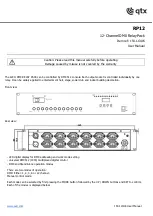
RP12
Brand: Qtx Pages: 4

TIR Two
Brand: PickData Pages: 4

Smart Energy Relay
Brand: SolarEdge Pages: 23

CL-PK-CPMR2)
Brand: Climax Pages: 2

SRW01-ETH Series
Brand: WEG Pages: 38


