background image

 CATALOGUE  

USE - MAINTENANCE 

AND SPARE PARTS

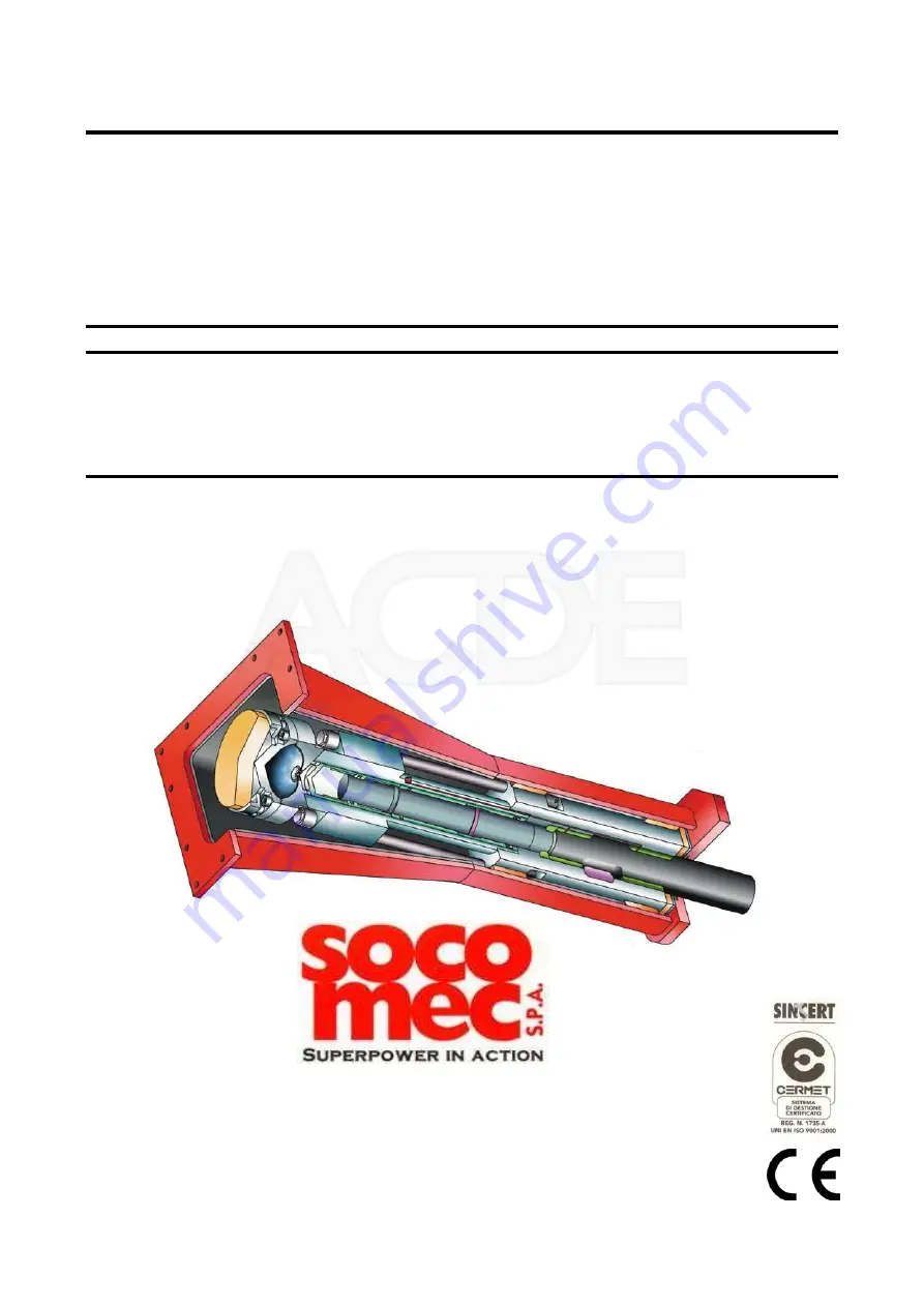
Hydraulic Demolition Breaker 

 MDO 1600 TS


Before carrying out any operation with or on the machine, you must 

read    

 carefully and understand each individual instruction written in this 

manual 

43014 Medesano (Parma) Italia - Strada Ferrari, 38 

Phone +39 0525 - 420929 - Fax +39 0525 - 420375 

http://www.socomecspa.com 

E-mail: [email protected]

Nederland B.V.

Summary of Contents for MDO 1600 TS

Page 1: ... carrying out any operation with or on the machine you must read carefully and understand each individual instruction written in this manual 43014 Medesano Parma Italia Strada Ferrari 38 Phone 39 0525 420929 Fax 39 0525 420375 http www socomecspa com E mail info socomecspa com Nederland B V ...

Page 2: ... lack of knowledge of instructions must be prevented from using the machine Instructions msu be kept complete and readable in accessible location for operators This manual is to be given to any other user or following owner of the equipment This equipment can t be put in service if the carrier machine is not declared conform to the CE no 2006 42 directive MANUFACTURER Socomec S p A Strada Ferrari ...

Page 3: ...ntrolli 6 REGULATIONS AND GREASING SYSTEM 25 Regolazioni ed impianto ingrassaggio 7 SPARE PARTS 29 Parti di ricambio 8 GROUPS EXPLODED VIEW Esploso gruppi 9 SUPPORT AND BODY GROUP 31 Gruppo supporto e corpo 10 STROKE CHANGER 34 Variatore corsa 11 INTERNAL GROUP 36 Gruppo interno 30 12 BLOCK GROUP 38 Gruppo blocchetto 13 DISTRIBUTOR GROUP 40 Gruppo distributore 14 ACCUMULATOR GROUP 42 Gruppo accumu...

Page 4: ...Page 4 GREASING SYSTEM 46 16 Impianto ingrassaggio 17 REQUEST OF SPARE PARTS 48 Richiesta parti di ricambio of 48 Nederland B V ...

Page 5: ...quipments safety glasses dust mask helmet earmufes etc Large and loose clothes watches and other types of bracelets are dangerous The operator must not make use alcohol or drugs medicines which can produce sleepiness while working The working area must be indicated and illuminated The operator must follow the maintenance program proposed by the manufacturer and make sure that the hammer is in good...

Page 6: ...tion to prevent this being a source of danger to himself or those nearby The area surrounding the equipment is divided into two zones OPERATOR S ZONES These are the zones the operator has to work in while the equipment is working normally The operator s zones are to be considered as potentially dangerous areas In these areas which are indicated in the drawing below it is best for the safety of the...

Page 7: ...ed above and all that has been described in greater detail in the GENERAL WARNINGS AND RESIDUAL RISKS chapter In addition the user should affix the following pictograms on the equipment Do not repair or adjust while the engine is running Symbol Name It is obligatory to use protective goggles It is obligatory to wear work clothing It is obligatory to protect your hearing It is obligatory to wear pr...

Page 8: ...l to drive poles to cut and break asphalt surfaces The manufacture is in accordance with the European Directive 2006 42 CE and with the Noise Directive 2000 14 CE Socomec S p A warrants that its machines are manufactured according to the regulation quoted up above and puts the marking CE on them SERIAL NUMBER MODEL YEAR OF MANUFACTURE TECHNICAL FEATURES 8 Page of 48 2 Nederland B V ...

Page 9: ...um valve bar 180 Hammer weight in working conditions Kg 1650 Tool weight Kg 104 Pin retainer tool weight Kg 6 5 Pressure line pipe diameter EN 856 4SP G 1 Return line pipe diameter EN 853 2SN G 1 1 4 Tool diameter mm 130 Hammer height with tool without adapting plate mm 2345 Maximum length of the tool inner guide L mm 479 Maximum diameter in front and back the tool bushings mm 135 Maximum oil temp...

Page 10: ...nut rotation 60 65 Accumulator cover screw Nm 1100 Accumulator screw Nm 1100 Articulation plug Nm 150 Variator screw Nm 140 Block Screw Nm 250 2 3 Optimal environmental working conditions DENOMINATION Unit of Measurement VALUE between Temperature C 5 45 Humidity 40 90 2 4 Overall dimensions MDO 1600 TS TECHNICAL FEATURES 10 Page of 48 2 Nederland B V ...

Page 11: ...Screws BLOCK SIDE It s necessary to unscrew the long screws in order to remove the accumulator from the monoblock You will find here below the accumulator details with the long screws to be unscrewed highlighted TECHNICAL FEATURES 11 Page of 48 2 Nederland B V ...

Page 12: ...s connection Connect pressure line hose to the entry side IN Connect returne line hose to the exit side OUT Check in the technical specification paragraph the total weight of the hammer including the adapting plate and the tool already mounted In order to move the hammer safely when it is not coupled to the excavator it is necessary to have a suitable and safe lifting system as showed in the pictu...

Page 13: ...pling of the hammer 3 3 2 Uncoupling Place the hammer horizontally on the ground in a safe area Stall the hydraulic system of the excavator Close the hoses flow if possible Disconnect the hoses and close up the ends of the flexible hoses in order to prevent oil leaking and dirt intake Remove the connecting rod pin Remove the boom pin After unblocking the hydraulic system take the excavator boom ou...

Page 14: ...higher or lower number of revs can cause serious damages to the hammer 4 1 Instruction for use The hammer can work in all the positions allowed by the joints of the excavator boom as long as it is always pressed perpendicularly against the surface of the material to be demolished The operator must release the correct load pressure on the hydraulic pipe line to the hammer if it is too low it retain...

Page 15: ...s working we advice to shorten the distance between excavator and hammer as much as possible and to remove the cylinder piston rods only partially C D strokes never completely out Make sure that the tool does not slip from the surface see picture If the tool is place wrongly or holds weakly on the material the dangerous blank firing can occur Yes Yes No No D C YES NO USE OF THE HAMMER 15 Page of 4...

Page 16: ...g or breaking of the tool mainly if it is carried out while the hammer is working Do not remove big rocks with the help of the hammer frame some parts can unweld and the plate can warp Do not hammer on the same spot for more than thirty seconds In case of a very hard surface it is necessary to change position very often until you find a softer ground Never forget to pre heat the oil before beginni...

Page 17: ...avator supports the weight of the hammer but with the tool still touching the ground Get off the excavator after blocking the hydraulic system Check the weight of the pin in the technical specifications Catch on the prominent part with your gloves and place the pin on the ground Get on the excavator again and unblock the hydraulic system Lift the hammer vertically until the damaged tool slips off ...

Page 18: ...f walls and non reinforced concrete structures for stones and quite soft materials To be mounted on the whole range of hammers Small spade terminal tool ref E or asphalt cutter tool ref F Suitable for tracing the lines marking the limits of the diggings To be mounted only on small and medium hammers Chisel terminal tool ref B Used for mining in general It is essential in demolitions where a high c...

Page 19: ...GI 2 penetration Dripping point 200 220 C Temperature of use until t 170 180 C It is recommended to use possibly only Socomec grease for a longer life of the parts Other checks to be made on the hammer Make sure that there are no oil leakages along the tool sank Make sure that no cracks are evident on the frame or on the linking bracket 5 3 Checks to be made on the hydraulic system Temperature of ...

Page 20: ... in the case of excessive wear invert the assembly or change it c Check the wear of the tool bushings if the inside diameter is bigger than the value indicated in the technical specifications contact the technical assistance for the replacement of the bushes Stop at the end of a work with a hot hammer During the night drive the hammer vertically into the ground so that the condensed water can easi...

Page 21: ... after four or five blows just after touching the ground surface The piston is at the bottom of the automatic brake andthe tool is completely out In this case the material is usually soft The tool sticks out but it does not go in again It is necessary to load the hammer correctly and to try and keep a constant load It is possible to improve the operation by keeping the hammer as much vertical as p...

Page 22: ...he number of blows but the power decreases The tool support seat support ring is worn out The piston shortens its stroke Make sure that the tool support seat support ring is intact So to operate as follows 1 Lay the hammer on the ground and trace a mark on the tool at the level of the bush end 2 Remove the tool and make sure that the value between the mark and the plate end of the tool is lower or...

Page 23: ...e interested element All components of the structure and the moving parts Steel Accumulator diaphragm Rubber Upper and lower stroke end stoppers Synthetic rubber and steel Seals O rings Rubber teflon Soundproofing materials Synthetic rubber The accumulator contains nitrogen under pressure Before scrapping exhaust the nitrogen under pressure which is in the accumulator through the charging valve Th...

Page 24: ...including the tools and the retainer pins for the tool All those parts subject to wear and tear are excluded from warranty The warranty which the producer must grant by law is limited to the change and mending of the parts damaged by the manufacturer himself and this at his own choice The report on possible faults must be done by the customer within 8 days by registered letter No compensation for ...

Page 25: ...g H B Take off the spring C C Insert between the spring C and the collar of the small piston D the necessary number of washers E until the correct working pressure is achieved In order to know which is the correct number of washers to add you have to consider that one washer makes a variation on the working pressure of 7 bar The washers must have the following characteristics thickness 0 5 mm Øi 1...

Page 26: ... to Short you need to rotate 90 clockwise or anticlockwise the central screw with a screwdriver or with a wrench key by turning it with the split in vertical position as appears in picture 2 If you want to get back to Long Strokes you only have to rotate again 90 Picture 1 Long stroke position Picture 2 Short stroke position REGULATIONS AND GREASING SYSTEM 26 Page of 48 6 Nederland B V ...

Page 27: ...m it is necessary to follow the above scheme The hoses of the grease input and output have to be linked to the greasing pump In order to have a correct installation please read and follow the manual supplied by the lubrication system s manufacturer G grease P pump input T tank REGULATIONS AND GREASING SYSTEM 27 Page of 48 6 Nederland B V ...

Page 28: ...n and therefore increase the amount grease supplied Before putting once again in action the pump mount the plug with the copper washer fig 12 pos 2 Functional control occurs through the visible eccentric shaft fig 12 pos 3 The following diagram shows the values for setting purpose Before proceeding to the setting screw the register completely To set the grease supply unscrew the register as shown ...

Page 29: ... the following details a Exact name and reference number of the parts required these specifications can be taken in the list written in the following pages b Exact serial number of the hammer for which the spare parts are required To order the spare parts use the form at the end of this manual SPARE PARTS 29 Page of 48 7 Nederland B V ...

Page 30: ...Metal case Accumulator group Internal group Body group Stroke changer Support group Block group Distributor group GROUPS EXPLODED VIEW 30 Page of 48 8 Nederland B V ...

Page 31: ...11 14 8 16 18 10 9 17 17 16 18 6 2 5 1 13 B B 26 32 19 25 20 21 29 30 28 27 22 24 33 23 31 34 19 19 12 3 4 3 12 15 7 SUPPORT AND BODY GROUP 31 Page of 48 9 Nederland B V ...

Page 32: ... 15511500 STOP LATCH 1 16 B 17010500 LOCKING PIN 2 17 B 17012100 TIE ROD RETAINER 8 18 B 19511200 PLUG 2 19 A 00010393 SEAL 4 20 A 00010409 BONDED WASHER 1 21 A 00010430 BONDED WASHER 1 22 A 00010431 BONDED WASHER 2 23 A 00030653 ALLEN PLUG 2 24 A 00053237 UNIDIRECTIONAL VALVE 1 25 A 00331040 PLUG 1 26 A 00331071 PLUG 1 27 A 00332133 NIPPLE 1 28 A 00332140 REDUCTION 1 29 A 00332930 PLUG 1 BONDED W...

Page 33: ...33 Page of 48 9 SUPPORT AND BODY GROUP 33 B 15520130 1 34 B 15521120 BODY BUSH RING 1 BODY Ref Quantity Code Description Spare parts Refer to the exploded views of the previous pages Nederland B V ...

Page 34: ...44 39 41 43 45 36 35 38 40 42 46 37 STROKE CHANGER 34 Page of 48 10 Nederland B V ...

Page 35: ...9 A 00030665 SCREW 4 40 A 00331039 PLUG 41 A 03330370 ELASTIC PIN 1 42 A 03330458 SPRING 1 43 A 03330470 SPHERE 1 44 B 10011100 VARIATOR FLANGE 1 45 B 15522200 COMMUTATION SHAFT 1 1 46 B 15522300 VARIATOR BUSH 1 O RING Ref Quantity Code Description Spare parts Refer to the exploded views of the previous pages Nederland B V ...

Page 36: ...55 62 49 63 56 57 48 47 60 52 51 53 54 59 48 58 61 48 50 49 52 50 51 53 INTERNAL GROUP 36 Page of 48 11 Nederland B V ...

Page 37: ... 14530700 CUPPED SPRING WASHER 5 56 B 14630600 PILOTING PISTON 1 57 B 14630600 PILOTING GRINDED PISTON 1 1 58 B 15520210 LOWER BODY BUSH 1 59 B 15520300 UPPER BODY BUSH 1 60 B 15520420 PISTON 1 61 B 15520900 CENTRAL BODY BUSH 1 62 B 15530100 DISTRIBUTOR BUSH 1 63 B 15530700 DISTRIBUTOR VALVE 1 O RING Ref Quantity Code Description Spare parts Refer to the exploded views of the previous pages Nederl...

Page 38: ...85 69 82 77 93 73 72 64 88 83 81 86 89 68 65 84 75 80 67 69 79 67 87 78 70 90 91 74 92 76 71 71 66 65 67 79 94 BLOCK GROUP 38 Page of 48 12 Nederland B V ...

Page 39: ...31000 PLUG 1 78 A 00331038 PLUG 2 79 A 00331040 PLUG 2 80 A 00331043 PLUG 1 81 A 00331140 PLUG 1 82 A 00332124 NIPPLE 1 83 A 00332129 REDUCTION 1 84 A 03333397 WASHER 6 85 B 15530200 OGIVE 2 86 B 15530400 BUSH 1 87 B 15530500 OGIVE PLUG 2 88 B 15530600 OGIVE SEAT 1 89 B 15530900 SLIDING SPOOL 1 90 B 15531700 PLUG 1 91 B 15532200 SPRING GUIDE 1 92 B 15532400 SPACER VALVE 1 O RING 93 B 15532500 OIL ...

Page 40: ...101 96 98 100 99 97 DISTRIBUTOR GROUP 40 Page of 48 13 Nederland B V ...

Page 41: ...3330240 CYLINDRICAL PIN 1 98 B 07521200 RETAINER RING 4 99 B 14530410 UPPER TIE ROD NUT 4 100 B 15531300 NUT RETAINER 4 101 B 15532110 DISTRIBUTOR 1 PLUG Ref Quantity Code Description Spare parts Refer to the exploded views of the previous pages Nederland B V ...

Page 42: ...107 104 106 101 105 109 108 103 102 ACCUMULATOR GROUP 42 Page of 48 14 Nederland B V ...

Page 43: ... CHARGING VALVE 1 104 B 09041400 DIAPHRAGM 1 105 B 13040700 UPPER BUFFER 1 106 B 15540100 ACCUMULATOR BASE 107 B 15540210 ACCUMULATOR COVER 1 108 B 17040300 SCREW 12 109 B 20040500 SCREW 8 1 SEAL Ref Quantity Code Description Spare parts Refer to the exploded views of the previous pages Nederland B V ...

Page 44: ...117 120 116 122 115 A A 113 118 121 124 119 123 121 112 111 114 CASE 44 Page of 48 15 Nederland B V ...

Page 45: ...00 LONG GUIDE 117 B 15551400 LOWER PAD 1 118 B 15552110 GUARD 1 119 B 15552200 GUARD SPACER 6 120 B 15559140 CASE 1 121 B 30051210 PLUG 2 4 122 B 30051310 RETAINER HOLE PLUG 2 123 B 30052410 PLUG 1 124 B 30052810 PLUG 3 ADAPTING PLATE Ref Quantity Code Description Spare parts Refer to the exploded views of the previous pages Nederland B V ...

Page 46: ...129 132 125 134 127 128 126 133 130 133 131 GREASING SYSTEM 46 Page of 48 16 Nederland B V ...

Page 47: ...28 A 00031008 SCREW 2 129 A 00114722 GREASING PUMP 1 130 A 00114937 HOSE 131 A 00114938 HOSE 1 132 A 00331040 PLUG 2 133 A 00332133 NIPPLE 6 134 B 32030400 GREASE PUMP HYDRAULIC BLOCK 1 2 BONDED WASHER Ref Quantity Code Description Spare parts Refer to the exploded views of the previous pages Nederland B V ...

Page 48: ...____________________________________________________ C A P Postcode Code postal C P _____________________________________________________ Stato State Etat Pais ________________________________________________________________ P IVA V A T T V A IVA _____________________________________________________________ N Tel e fax _________________________________________________________________________ Marte...

Reviews: