background image


Copyright © 2011 SMSC or its subsidiaries. All rights reserved.
Circuit diagrams and other information relating to SMSC products are included as a means of illustrating typical applications. Consequently, complete information
sufficient for construction purposes is not necessarily given. Although the information has been checked and is believed to be accurate, no responsibility is
assumed for inaccuracies. SMSC reserves the right to make changes to specifications and product descriptions at any time without notice. Contact your local
SMSC sales office to obtain the latest specifications before placing your product order. The provision of this information does not convey to the purchaser of the
described semiconductor devices any licenses under any patent rights or other intellectual property rights of SMSC or others. All sales are expressly conditional
on your agreement to the terms and conditions of the most recently dated version of SMSC's standard Terms of Sale Agreement dated before the date of your
order (the "Terms of Sale Agreement"). The product may contain design defects or errors known as anomalies which may cause the product's functions to deviate
from published specifications. Anomaly sheets are available upon request. SMSC products are not designed, intended, authorized or warranted for use in any life
support or other application where product failure could cause or contribute to personal injury or severe property damage. Any and all such uses without prior
written approval of an Officer of SMSC and further testing and/or modification will be fully at the risk of the customer. Copies of this document or other SMSC
literature, as well as the Terms of Sale Agreement, may be obtained by visiting SMSC’s website at http://www.smsc.com. SMSC is a registered trademark of
Standard Microsystems Corporation (“SMSC”). Product names and company names are the trademarks of their respective holders. 
SMSC DISCLAIMS AND EXCLUDES ANY AND ALL WARRANTIES, INCLUDING WITHOUT LIMITATION ANY AND ALL IMPLIED WARRANTIES OF MERCHANTABILITY,
FITNESS FOR A PARTICULAR PURPOSE, TITLE, AND AGAINST INFRINGEMENT AND THE LIKE, AND ANY AND ALL WARRANTIES ARISING FROM ANY COURSE
OF DEALING OR USAGE OF TRADE. IN NO EVENT SHALL SMSC BE LIABLE FOR ANY DIRECT, INCIDENTAL, INDIRECT, SPECIAL, PUNITIVE, OR CONSEQUENTIAL
DAMAGES; OR FOR LOST DATA, PROFITS, SAVINGS OR REVENUES OF ANY KIND; REGARDLESS OF THE FORM OF ACTION, WHETHER BASED ON CONTRACT;
TORT; NEGLIGENCE OF SMSC OR OTHERS; STRICT LIABILITY; BREACH OF WARRANTY; OR OTHERWISE; WHETHER OR NOT ANY REMEDY OF BUYER IS HELD
TO HAVE FAILED OF ITS ESSENTIAL PURPOSE, AND WHETHER OR NOT SMSC HAS BEEN ADVISED OF THE POSSIBILITY OF SUCH DAMAGES.
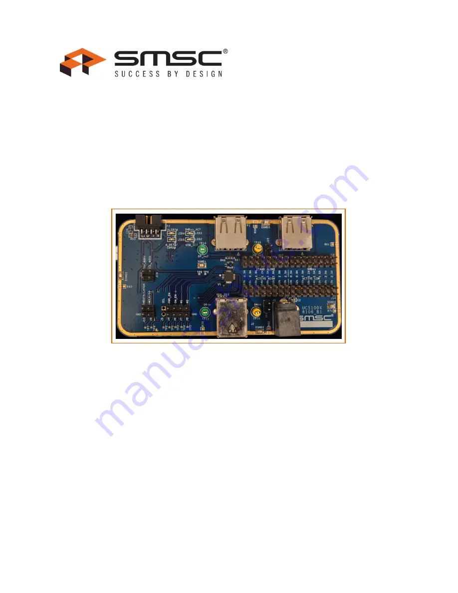
SMSC EVB-UCS1002

Revision 1.1 (09-30-11)

PRELIMINARY - SMSC CONFIDENTIAL

UCS1002 EVB User Manual

Summary of Contents for UCS1002 EVB

Page 1: ...authorized or warranted for use in any life support or other application where product failure could cause or contribute to personal injury or severe property damage Any and all such uses without prior written approval of an Officer of SMSC and further testing and or modification will be fully at the risk of the customer Copies of this document or other SMSC literature as well as the Terms of Sale...

Page 2: ...anual UCS1002 Datasheet SCH 8106 UCS100x Evaluation Board Schematic EVB Bill of Material 1 2 UCS1002 Evaluation System The evaluation system has several components as shown in Figure 1 1 Customer provided Windows PC SMSC UCS100X graphical user interface GUI software based on National Instruments LabVIEW software and SMSC USB Bridge Driver SMSC UCS100x Evaluation Board USB Cable for GUI communicati...

Page 3: ... EVB User Manual Revision 1 1 09 30 11 3 SMSC EVB UCS1002 PRELIMINARY SMSC CONFIDENTIAL 1 2 1 Block Diagram A block diagram of the UCS1002 EVB is shown in Figure 1 2 below Figure 1 2 UCS1002 EVB Block Diagram ...

Page 4: ...t Angle Power Supply This connects directly to the UCS100x VS input pins P1 Right Angle USB Standard A Receptacle This connects the EVB to the portable device P2 Right Angle Receptacle for Factory Use Onlyl This is a programming port for the 8051 micro controller P3 Right Angle USB Mini B Receptacle This connects the EVB to the PC with the GUI software UCS1002 only It also provides 5V power to the...

Page 5: ...e LEDs LED2 USB Activity When lit this yellow LED means 5V power is applied to the USB bridge IC LED3 SMBus Activity When flashing this yellow LED indicates SMBus communication activity LED4 ALERT When lit this red LED indicates an alert signal is active LED5 A_DET CHRG When lit this green LED indicates a device is attached for the UCS1002 Figure 1 4 EVB Top View LEDs ...

Page 6: ... 1 5 shows the top of an EVB and highlights the jumpers J4 PWR_EN When installed this jumper will force a low at the PWR_EN pin J5 Not Used The jumper is not used J6 EM_EN When installed this jumper will force a low at the EM_EN pin J7 M1 When installed this jumper will force a low at the M1 pin Figure 1 5 EVB Top View Jumpers ...

Page 7: ...er connects the 5V pin of connector J2 to the UCS1001 or UCS1002 VS power input pins It MUST be left out if external power supply is connected to J3 J12 Current Limit Current Limit UCS1002 in SMBus mode only This jumper selects the current limit This is used with the UCS1002 only J13 Current Limit Stand alone Current Limit This jumper selects the current limit This is used with the UCS1001 and the...

Page 8: ... TP10 DMin This test point connects to the DMin data line through a 1M Ohm series resistor TP11 DPin This test point connects to the DPin data line through a 1M Ohm series resistor TP14 DP_out This test point connects to the DP_out data line through a 1M Ohm series resistor TP16 DM_out This test point connects to the DM_out data line through a 1M Ohm series resistor Figure 1 6 EVB Top View Data Te...

Page 9: ...ts Signal Ground This test point connects to the signal ground of the EVB This is the ground reference for the UCS100X Earth Ground This test point connects to the earth ground of the EVB This ground is connected to the signal ground at one location via a 0 ohm resistor U1 UCS100X This part will be populated with either the UCS1002 UCS1001 1 or the UCS1001 2 Figure 1 7 EVB Top View Ground Test Poi...

Page 10: ... based computer with a USB port 2 1 GUI Software Installation Begin by inserting the CD provided with the EVB into the computer Run the Setup exe program located in the root directory of the CD This steps through the UCS100X GUI installation which takes less than a minute Figure 2 1 shows the initial installation screen which displays briefly as the setup program loads Figure 2 1 Software Installa...

Page 11: ...peration the files must be installed in the default locations The default location for the software files is C Program Files SMSC UCS100X and for the LabVIEW software is C Program Files National Instruments In order to use this SMSC software the license agreement must be accepted see Figure 2 3 Figure 2 2 Software Installation Step 2 Figure 2 3 Software Installation Step 3 ...

Page 12: ...ion shortcuts will be created on the Windows Start Menu under Programs SMSC UCS1002 and on the desktop When installation is complete the program will automatically run see Figure 2 5 The UCS1002 GUI will have SMBus communications Note Screen captures in this document were taken on a PC with Windows XP using the default desktop colors The colors on your screen may vary especially if a Windows theme...

Page 13: ...talled on the selected USB port the Find New Hardware wizard will pop up on the PC s screen Follow the on screen instructions to complete the installation process The files will automatically be retrieved from the CD See Figure 2 6 through Figure 2 10 for a step by step view of the installation If installation of driver on Windows 7 PC please see included Installation Note located on CD Figure 2 5...

Page 14: ...CS1002 EVB User Manual SMSC EVB UCS1002 11 Revision 1 1 09 30 11 PRELIMINARY SMSC CONFIDENTIAL Figure 2 7 SMSC USB Bridge Driver Installation Step 3 Figure 2 8 SMSC USB Bridge Driver Installation Step 4 ...

Page 15: ...UCS1002 EVB User Manual Revision 1 1 09 30 11 12 SMSC EVB UCS1002 PRELIMINARY SMSC CONFIDENTIAL Figure 2 9 SMSC USB Bridge Driver Installation Step 5 ...

Page 16: ... behavior report and disconnect is the default 3 2 EVB Power Source This EVB requires a single USB cable to operate USB bus voltage is provided to the onboard indicator LEDs and the SMSC USB Bridge This bridge regulates the 5V USB power to 3 3V used by the EVB circuitry 3 3 VS 5V Power Source A 5V power source is needed for VS to charge the portable device This can come from a PC USB port limited ...

Page 17: ...UCS1002 EVB User Manual Revision 1 1 09 30 11 15 SMSC EVB UCS1002 PRELIMINARY SMSC CONFIDENTIAL Figure 3 1 UCS100X to SMBus Bridge Jumpers ...

Page 18: ...able 3 1 Table 3 1 LED Status Indicators LED SIGNAL OFF GREEN RED YELLOW 2 USB Activity No activity on USB port N A NA Activity on USB port 3 SMBus Activity No Activity within USB SMBus bridge N A N A Activity within USB SMBus bridge 4 ALERT ALERT pin is not asserted N A ALERT pin is asserted N A 5 A_DET CHRG A device is not attached A device is attached N A N A ...

Page 19: ...per voltage input to power switch coming from auxiliary power input J3 Jumper voltage input to power switch coming from host J2 J12 SMBus Applicable only to UCS1002 Jumpered pins select the corresponding resistor which selects the ILIM setting J13 STAND ALONE Applicable only to UCS1001 and UCS1002 in stand alone mode Jumpered pins select the corresponding resistor which selects the ILIM setting J1...

Page 20: ...elect Programs SMSC UCS100X 2 Connect the USB mini connector end of the cable to the EVB and the standard USB connector of the cable to any available USB port on the PC The USB Activity LED should light indicating that the EVB is getting power Table 3 3 Test Points TEST POINT SIGNAL FUNCTION MONITORED 1 PWR_EN 2 N A 3 EM_EN 4 M1 5 M2 6 SMCLK S0 7 SMDATA LATCH 8 ALERT 9 A_DET CHRG 10 DMin 11 DPin 1...

Page 21: ... controls on the GUI panel hovering the mouse cursor over a control will pop up context help that indicates the register address or gives a description In addition a context help window can be displayed by clicking the Help menu and then selecting Show Context Help Display speed varies by system After a power up of the EVB the default settings are loaded Users can save setting configurations to us...

Page 22: ...harger DCE dedicated charger emulation DCP dedicated charging port EM emulation EM_EN emulation enable M1 mode control pin number one M2 mode control pin number two 5 2 2 Keyboard Shortcuts Some GUI controls have keyboard shortcuts as shown in Table 5 1 Table 5 1 UCS1002 EVB GUI Keyboard Shortcuts GUI CONTROL SHORTCUT CONTROL DESCRIPTION Run CTRL R Section 6 1 1 Stop and Run Buttons Stop F12 Secti...

Page 23: ... section on the right side of the GUI shown in Figure 6 1 affects GUI operation This section is always displayed 6 1 1 Stop and Run Buttons The Stop button shown in Figure 6 1 halts GUI software communication with the EVB When this button is clicked the Run button which has an arrow on it displays below the menu bar as shown in Figure 6 2 Figure 6 1 Panel Controls Figure 6 2 Run Button ...

Page 24: ...rol panel update speed It affects the speed that the software reads the registers but will not affect the device s sampling time The default is 50 ms This number can range from 0 to 5000ms in increments of 25ms 6 1 4 Single Continuous Read The panel defaults to continuous register reads toggle switch in down position as shown in Figure 6 1 To stop continuous register reads click the Single Read En...

Page 25: ...device attached respectively When the indicators are dark the pin states are high 6 2 2 Pin Indicators The pin indicators SEL PWR_EN M1 M2 and EM_EN shown in Figure 6 3 are green if the signal on the corresponding pin on the UCS1002 device is high and dark if the signal is low If the Pin Ignore box is checked see Section 6 2 3 Pin Override these indicators reflect the GUI overrides for these pins ...

Page 26: ...nce by the UCS1002 at power up so there is no pin override for it To close the port power switch the PWR_EN state must match the SEL state e g SEL high and PWR_EN high 6 3 Charger Emulation Selection The Charger Emulation Selection section on the right side of the GUI shown in Figure 6 4 provides a quick reference regarding operating state based on the values of M1 M2 and EM_EN This section is alw...

Page 27: ...ss than maximum current limit and power state e g detect active error etc When a portable device has been successfully attached the screen shows the power state change from Detect to Active and shows the various handshakes applied Once it is determined that the device is charging the screen shows which emulation profile was successful and the graph shows the charging current Optionally the user ma...

Page 28: ...following 1 Connect VS to the EVB see Section 3 6 Jumper Settings The VS Low indicator on the Main Tab must be dark If the VS Low indicator is red the voltage is not high enough to charge a portable device 2 Connect a portable device to the EVB Use the OEM USB charging cable that came with the portable device 3 The UCS1002 should detect an attachment switch to the Active power state apply an emula...

Page 29: ...Port CDP The CDP charging profile is based on the Battery Charging standard 1 x When a BC1 x compliant portable device attachment is detected the UCS1002 and the portable device do handshaking based on the standard If handshaking is successful charging occurs up to the set current limit To select the CDP port power profile M1 M2 and EM_EN must all be high This can be done by removing the jumpers f...

Page 30: ... speed data switch and supplies current up to the current limit To select Data Pass Through M1 M2 and EM_EN can be set to any one of the two data pass thru combinations 010 and 110 as shown in Figure 7 4 This can be done by setting the jumpers for these pins J7 J8 and J6 respectively Section 3 6 Jumper Settings or by using the pin override in the GUI see Section 6 2 3 Pin Override Figure 7 4 Data ...

Page 31: ... Connect VS to the EVB see Section 3 6 Jumper Settings The VS Low indicator on the Main Tab must be dark If the VS Low indicator is red the voltage is not high enough to charge a portable device 4 Connect a portable device to the EVB Use the OEM USB charging cable that came with the portable device 5 Enable Rationing Place a checkmark in the Ration Enable box on the Main Tab 6 Watch the GUI as the...

Page 32: ...on controls Items are grouped by function 8 1 Interrupt Status Indicators in the Interrupt Status section turn green when the corresponding bit is high and are dark when the bit is low 8 2 General Status Indicators in the General Status section turn green when the corresponding bit is high and are dark when the bit is low 8 3 Emulation Behavior Place a checkmark in a box to enable the correspondin...

Page 33: ...8 7 Fault Handler Controls related to fault handling 8 8 General Control Controls for general parameters 8 9 Thermal Regulation Controls for thermal and detection delay parameters 8 10 Port Power Keep out Displays values for the port power parameters 8 11 General Emulation Charging Settings Controls for emulation and charging 8 12 Emulation Timeouts Sets the emulation timeout period for each profi...

Page 34: ...tion note 9 1 Custom Emulation Configuration Creating a custom emulation profile is a two part process of entering the appropriate stimulus response pairs in the fields provided as well as the desired current limiting behavior after emulation is applied and the portable device starts to draw current 9 1 1 Example The settings shown in Figure 9 1 will apply the Legacy 1 stimulus pair This includes ...

Page 35: ...h that profile Emulation Timeout will also be loaded based on the settings of the corresponding Emulation Timeout on the Configuration General Status tab 9 4 Save Custom Emulation Configuration Customs Emulation Configuration allows for a quick way to save to a file the neccesary registers to configure the UCS1002 for a custom profile Enter the path and press the SAVE button Files will be overwrit...

Page 36: ...to note that not all addresses are physical memory locations on the device these registers will read 0 Likewise some registers shown that are undocumented in the datasheet may have data Editing these registers can cause unexpected results To update a register value locate the register address in the left column type the new value in the corresponding cell in the right column and press the Enter ke...

Page 37: ...rmation shown in Figure 10 1 shows the values of three registers FDh FEh and FFh which identify the device on the EVB 10 3 GUI Information Check for GUI Update requires an internet connection When pressed it will check with SMSC if the current version is up to date and will automatically download a zip file if out of date The Documentation button will launch a Windows file viewer opening the local...

Page 38: ...dows based navigation aid to select the folder where the configuration file will be saved The file should be named with the extension txt or similar text file format Once a file name and location has been chosen click the Save All Register Values switch and the file is saved Note If a file with the same name already exists the file will be overwritten and old data will be lost The data is saved in...

Page 39: ...e potential of the UCS1002 11 1 Step 1 Configure Device for Demo Routine The first step in preparing to run the Demo feature is to configure the device to the desired starting configuration A file has been pre loaded at installation that can be used or a new configuration can be created Each time the Demo button in the Panel Control section is toggled the Configuration Setup file will be loaded 11...

Page 40: ...et will start the demo after the initial cycle after the specified Dead Batt Delay time This is useful when the battery is completely discharged and the device OS is unable to handshake with UCS1002 Dead Batt Delay defined in minutes Minimum is 0 minutes maximum is 10 minutes Current Reading Select either the End Value last value before PWR_EN set low or MAX Value highest value during Dwell Time 1...

Page 41: ... Reconnect the EVB then restart the GUI 12 3 Random Panel Display When an EVB is not connected to the PC running the GUI the panel will be in an all zero register displayed state This also occurs when SMBus communications are disconnected The panel display is not meaningful Connect the EVB and establish SMBus communications If this still doesn t work there s a problem with the connection The cable...

Page 42: ...ped positions between Default and Alternate for M1 M2 and EM_EN jumpers Rev 0 1 07 07 11 Updated screen shots for Config Gen Status Replaced Rev 0 09 06 20 11 Updated screen shots for selector and Config Gen Status Replaced Rev 0 08 06 17 11 Updated screen shots Replaced Rev 0 07 06 16 11 Split LEDs and Connector section added data test points and ground test point sections Described legacy 1 in C...

Reviews: