


Hussar Robot Chassis Manual
Smart Restaurant Solutions
1
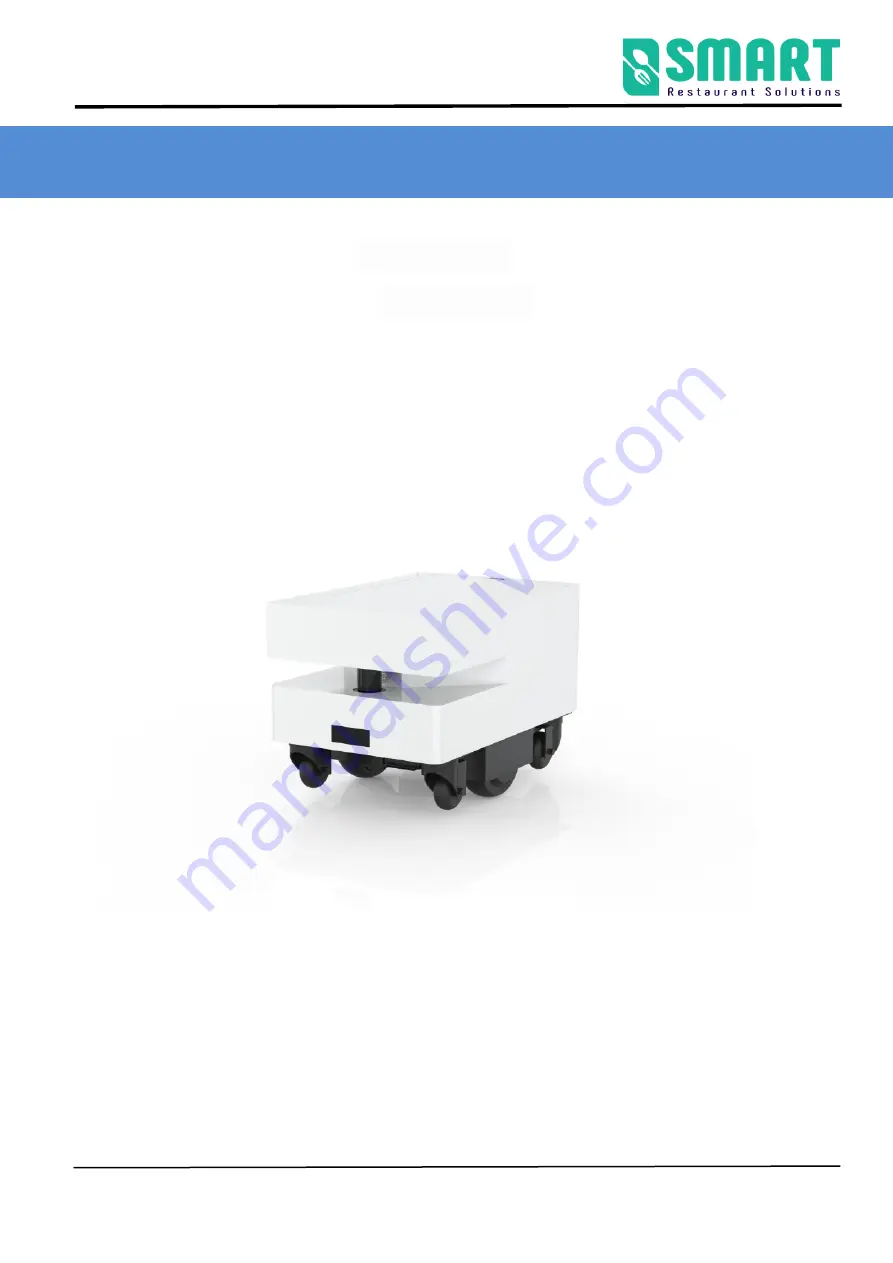
Hussar Robot Chassis Manual
Version : 2.1.4G
Date : 2022-1-6
Note: This document provides the deployment process and precautions
related to the machine. Follow the instructions in the document to avoid
abnormal situations when the machine is used later.


