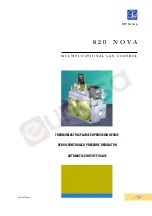
background image

8 2 0   N O V A

M U L T I F U N C T I O N A L   G A S   C O N T R O L

THERMOELECTRIC FLAME SUPERVISION DEVICE

SERVO-CONTROLLED PRESSURE REGULATOR

AUTOMATIC SHUT-OFF VALVE

SIT Group

PIN 63AP7060/2

Summary of Contents for 820 NOVA

Page 1: ...8 2 0 N O V A M U LT I F U N C T I O N A L G A S C O N T R O L THERMOELECTRIC FLAME SUPERVISION DEVICE SERVO CONTROLLED PRESSURE REGULATOR AUTOMATIC SHUT OFF VALVE SIT Group PIN 63AP7060 2 ...

Page 2: ...tions Thermoelectric flame supervision device with re start interlock Near silent shut off valve Servo controlled pressure regulator Step opening ignition device optional Main gas flow control optional Pilot outlet with gas flow adjustment screw Inlet and pilot filters Inlet and outlet pressure test points Threaded gas inlet and outlet with provision for flange connection Connection for combustion...

Page 3: ...ber pressure regulator compensation 1 Control knob 2 Pressure regulator cap screw 3 Pilot gas rate adjuster 4 Thermocouple connection 5 Alternative thermocouple connection 6 Provision for accessories support bracket 7 Inlet pressure test point 8 Outlet pressure test point 7 8 9 6 10 11 2 1 3 4 12 5 13 Gas connections Rp 1 2 ISO 7 Installation positions any Gas families I II and III Maximum gas inl...

Page 4: ...Family d 0 45 Q 7 5 m3 h p 5 mbar II Family d 0 6 Q 6 5 m3 h p 5 mbar III Family d 1 7 Q 8 1 kg h p 5 mbar CLASS C I Family d 0 45 Q 5 3 m3 h p 5 mbar II Family d 0 6 Q 4 6 m3 h p 5 mbar III Family d 1 7 Q 5 8 kg h p 5 mbar CLASSE D CLASSE C 0 5 10 Q m3 h d 0 6 4 2 6 8 10 p mbar CLASS D CLASS C ...

Page 5: ...ition device reach the maximum rate of flow after approx 10 seconds Pilot position To keep the main burner off and the pilot flame on slightly depress the control knob and rotate to Pilot Shut down Slightly depress the control knob and rotate to Off fig 3 CAUTION The re start interlock device prevents the appliance from re igniting until the flame supervision device has interrupted the gas flow Af...

Page 6: ...ovided Torque 1 Nm Electrical connections The use of special connectors is recommended for the mains powered versions In order to ensure that the valve is connected to the appliance s earth circuit always use the power connector with the earth terminal fixing it with the appropriate screw The 24 VAC versions must be powered by an isolating transformer at a very low safety voltage as per EN 60742 U...

Page 7: ...vant screw clockwise to decrease the gas flow and anticlockwise to increase it Overriding the pilot flow adjustment function Fully tighten the adjustment screw and then unscrew two complete turns Changing the gas family or group Check that the appliance is suitable for operation with the gas family or group in question Following the instructions given above adjust the outlet pressure to the values...

Page 8: ...820 NOVA Multifunctional control for electrically powered gas appliances 9 955 911 R00 GRAPHIC DESIGN BY START PD ITALY ...

Reviews: