SI Nano Box 275, Installation Instruction
The SI Nano Box 275 is a cutting-edge digital device designed for seamless connectivity. For easy installation and setup, detailed Installation Instructions are provided in the user manual. Download the manual for free from our website to unlock the full potential of your Nano Box 275.
Share
Download


Reviews:
No comments
Related manuals for Nano Box 275
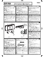
MultiSync P701
Brand: NEC Pages: 2

2247
Brand: NCR Pages: 12

3500
Brand: F-H-S Pages: 17

Lindau
Brand: Stein HGS Pages: 8

BT8385-CTW
Brand: B-Tech Pages: 8

KingJoe Pro 2
Brand: Yakima Pages: 30

LC-50
Brand: Solarix Pages: 14

CONCEPT HOUSWARES PR-40322
Brand: PR Housewares Pages: 2

OM1004283
Brand: Omnimount Pages: 32

Helios T3260
Brand: Audio Solutions Pages: 8

FSA-1015
Brand: CHIEF Pages: 8

The Original Arched
Brand: CATCHPOLE & RYE Pages: 5

H-7896
Brand: U-Line Pages: 9

EVA-UB4
Brand: Nittan Pages: 6

CCS-UC-200-WSTND
Brand: Crestron Pages: 2

PD032001-P0
Brand: SMS Pages: 14

BT9920
Brand: B-Tech Pages: 12

DDR1732DAL
Brand: Tripp Lite Pages: 50


