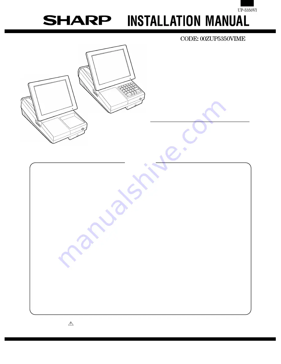
background image

POS TERMINAL 

MODEL

 UP-5350 

("V" version) 

For KB version

For TQ,TS,KA version

 1. Removing the Rear display filter . . . . . . . . . . . . . . . . . . . . . . . . . . . . . . . . . . . . . . . . . . . . . . .  1 

 2. Replacing the Rear display filter . . . . . . . . . . . . . . . . . . . . . . . . . . . . . . . . . . . . . . . . . . . . . . .  1 

 3. Removing the Top cabinet . . . . . . . . . . . . . . . . . . . . . . . . . . . . . . . . . . . . . . . . . . . . . . . . . . . .  1 

 4. Replacing the Top cabinet . . . . . . . . . . . . . . . . . . . . . . . . . . . . . . . . . . . . . . . . . . . . . . . . . . . .  1 

 5. Removing the power supply unit and AC cord. . . . . . . . . . . . . . . . . . . . . . . . . . . . . . . . . . . . .  2 

 6. Replacing the power supply unit and AC cord. . . . . . . . . . . . . . . . . . . . . . . . . . . . . . . . . . . . .  2 

 7. Removing the LCD unit . . . . . . . . . . . . . . . . . . . . . . . . . . . . . . . . . . . . . . . . . . . . . . . . . . . . . .  2 

 8. Replacing the LCD unit . . . . . . . . . . . . . . . . . . . . . . . . . . . . . . . . . . . . . . . . . . . . . . . . . . . . . .  3 

 9. Replacing the FDD unit . . . . . . . . . . . . . . . . . . . . . . . . . . . . . . . . . . . . . . . . . . . . . . . . . . . . . .  4 

10. Removing the FDD unit. . . . . . . . . . . . . . . . . . . . . . . . . . . . . . . . . . . . . . . . . . . . . . . . . . . . . .  5 

11. D-RAM disk: S.O. DIMM (Locally supplied) . . . . . . . . . . . . . . . . . . . . . . . . . . . . . . . . . . . . . .  5 

12. MCR unit: UP-E12MR2 . . . . . . . . . . . . . . . . . . . . . . . . . . . . . . . . . . . . . . . . . . . . . . . . . . . . . .  6 

13. Adjusting the IRQ10/11 on the ISA PWB.. . . . . . . . . . . . . . . . . . . . . . . . . . . . . . . . . . . . . . . .  6 

14. RS232 & CENTRO I/F: ER-A8RS. . . . . . . . . . . . . . . . . . . . . . . . . . . . . . . . . . . . . . . . . . . . . .  6 

15. Rear display UP-I20DP . . . . . . . . . . . . . . . . . . . . . . . . . . . . . . . . . . . . . . . . . . . . . . . . . . . . . .  7 

16. Pole display: UP-P20DP . . . . . . . . . . . . . . . . . . . . . . . . . . . . . . . . . . . . . . . . . . . . . . . . . . . . .  7 

17. Drawer unit: ER-03DW/04DW/05DW . . . . . . . . . . . . . . . . . . . . . . . . . . . . . . . . . . . . . . . . . . .  9 

18. COM1, COM2, COM3/5, and COM4/6 Connector . . . . . . . . . . . . . . . . . . . . . . . . . . . . . . . .  10 

19. Built-in printer: UP-T80BP. . . . . . . . . . . . . . . . . . . . . . . . . . . . . . . . . . . . . . . . . . . . . . . . . . .  11 

20. Key pad : UP-C30PK . . . . . . . . . . . . . . . . . . . . . . . . . . . . . . . . . . . . . . . . . . . . . . . . . . . . . .  15 

CONTENTS

SHARP CORPORATION

Parts marked with "

" is important for maintaining the safety of the set. Be sure to replace these parts with specified

ones for maintaining the safety and performance of the set.

This document has been published to be used 
for after sales service only.
The contents are subject to change without notice.

Summary of Contents for UP-5350

Page 1: ...MM Locally supplied 5 12 MCR unit UP E12MR2 6 13 Adjusting the IRQ10 11 on the ISA PWB 6 14 RS232 CENTRO I F ER A8RS 6 15 Rear display UP I20DP 7 16 Pole display UP P20DP 7 17 Drawer unit ER 03DW 04DW 05DW 9 18 COM1 COM2 COM3 5 and COM4 6 Connector 10 19 Built in printer UP T80BP 11 20 Key pad UP C30PK 15 CONTENTS SHARP CORPORATION Parts marked with is important for maintaining the safety of the s...

Page 2: ... Replacing the Rear display filter Install the Rear display filter in the reverse order of removing 3 Removing the Top cabinet 1 Remove the two Screws 2 Remove the Side cabinet 3 Remove the Screw 4 Remove the Printer cover 5 Remove the Screw 6 Remove the Top cabinet a Release the latches and in that order Slide the upper cabinet to the right and release the latch on the right b Lift the top cabine...

Page 3: ...e installing make sure that each connector is connected se curely When connecting the AC cord to the power supply unit in assembly tighten with the torque of 3 kg cm 1 kg cm 7 Removing the LCD unit 1 Remove the LCD unit a Remove the screw b Remove the tilt cover c Remove the core d Remove the three Screws 2 Remove the LCD rear cabinet a Remove the two Screws b Remove the pawls to of the LCD rear c...

Page 4: ...move the Inverter cable d Remove the two Screws 5 Remove the LCD a Remove the six screws b Remove the four screws c Remove the LCD plate d Remove the LCD PWB unit e Remove the screw and LED PWB Reference for attaching LCD GUM A to LCD GUM B 7 8 6 5 9 9 Lock Unlock Lock Unlock 10 11 12 13 15 14 14 21 20 19 18 17 18 18 18 18 18 19 19 22 23 b a b a Reference line Reference line Reference line Referen...

Page 5: ...stall the FDD ANGLE A a Install the two FDD ANGLE A and EARTH WIRE to the FDD UNIT with the four screws 5 Connect the FDD CABLE to the FDD UNIT 6 Install the ferrite core onto the FDD cable 7 Install the FDD UNIT to the UP 5350 a Install the FDD UNIT and FDD ANGLE B to the bottom cabinet with the four screws b Connect the FDD CABLE to the Main PWB c Pass the EARTH WIRE through the hole d Install t...

Page 6: ...ytes 32Mbytes 64Mbytes Type EDO type Access time 60 nsec less than Power 3 3V Refresh cycle 1024 16 msec 2048 32 msec 4096 64 msec 4096 64 msec Refresh type CBR Power consumption 700 mA less than Other 4 chips x 16Mbits 1Mwords x 16 bits 8chips x 16Mbits 2 Mwords x 8 bits 4 chips x 64Mbits 4 Mwords x 16 bits 8 chips x 64Mbits 8 Mwords x 8 bits 1 Remove the top cabinet 2 Install the option D RAM di...

Page 7: ...e ISA Slot M OFF Connect IRQ10 to GND not to the ISA Slot S2 IRQ11 S ON Connect IRQ11 to the ISA Slot M OFF Connect IRQ11 to GND not to the ISA Slot 14 RS232 CENTRO I F ER A8RS Adjust the IRQ10 and IRQ11 See the 13 Adjusting the IRQ10 11 on the ISA PWB 1 Remove the REAR COVER 2 Remove the screw from the ISA BUS SHASSIS 3 Insert the I F PWB to the ISA BUS CONNECTOR 4 Fix the I F BRACKET to the ISA ...

Page 8: ...ing boss of the bottom cabinet with the angle hole in the display unit 16 Pole display UP P20DP 1 Install the core to the display cable and the display earth cable 2 Connect the Display cable to the remote display connector on the back of the set 3 Fix the display cable with the cable holder and tighten the screw on the back of bottom cabinet 4 Fix the display earth cable to the main chassis with ...

Page 9: ... should be used instead of the standard cable and earth wire if the UP 20DP s standard pole is removed to lower the height of the UP 20DP 1 Earth wire S 1 1 Remove the five screws 2 Remove the Base angle 3 Remove the PWB unit from the Base cabinet 4 Remove the display cable from the PWB unit 5 Remove the two screws 6 Remove the Base cabinet from the pole cabinet 7 Pull the Ratchet attached to the ...

Page 10: ...l table 4 Lowering the height of the UP P20DP Remove the standard Pole and attach the Base cabinet to the Ratch At this time replace the standard Display cable and the Earth wire with the S type cable and wire 17 Drawer unit ER 03DW 04DW 05DW 1 Connect the drawer cable to the drawer connector 2 Fix the earth wire to the main chassis from drawer box unit with the screw 3 Install the ferrite Core to...

Page 11: ...pecifications D SUB9 Pin No Signal Function I O 1 CD Data Carrier Detect I 2 RD Receive Data I 3 SD Send Data O 4 ER Data Terminal Ready O 5 SG Signal Ground 6 DR Data set Ready I 7 RS Request to Send O 8 CS Clear to Send I 9 CI 5V Ring Indicate 5V I Main PWB S2 COM1 1 5V 3 CI S1 COM2 1 5V 3 CI S2 1 3 S1 1 3 S2 3 1 5V CI 3 5V 1 S1 CI 3 1 S2 5V CI 3 1 S1 5V CI 5V CI COM2 COM1 ...

Page 12: ...G Signal Ground 6 RD Receive Data I 7 DR Data set Ready I 8 CS Clear to Send I 19 Built in printer UP T80BP 1 Remove the BOTTOM PLATE a Remove the three SCREWs b Remove the BOTTOM PLATE c Remove the SCREW CABLE CLAMP and POWER SUP PLY CABLE Fig 1 2 Install the PS CONTROL PWB a Fix the PS CONTROL PWB with three SCREWs SCREW Use the screw which was fixing the CLAMP 3 Connect the POWER SUPPLY CABLE t...

Page 13: ...awl b Pass the SWITCH UNIT CABLE through the hole B Fig 4 8 Install the AUTO CUTTER RELAY PWB UNIT a Install the AUTO CUTTER RELAY PWB UNIT with SCREW b Pass the AUTO CUTTER RELAY PWB CABLE through the hole C Fig 5 9 Install the PAPER GUIDE to the PRINTER UNIT 10 Install the HEAD CABLE to the PRINTER UNIT Fig 6 10 9 11 12 A A B 12 13 14 15 C 16 XEBSD30P08000 15 17 19 18 ...

Page 14: ...or each cables as shown below 13 Connect the Printer cables to the CONTROL PWB a SWITCH UNIT CABLE Connect to the CN7 b HEAD CABLE Connect to the CN5 Attach the FERRITE CORE L size and CA BLE CLAMP Fix the CABLE CLAMP with a SCREW c AUTO CUTTER RELAY PWB CABLE Connect to the CN4 d MOTOR CABLE Connect to the CN2 e SENSOR CABLE Connect to the CN6 Fig 8 C D 18 23 a 23 b 23 c 23 d 14 19 22 25 24 21 20...

Page 15: ...FERRITE CORE S size to the I F CABLE b Fix the I F CABLE and EARTH WIRE with the CABLE BAND c Set the switch SW2 to the MRS position Fig 9 15 Install the BOTTOM PLATE Fig 10 16 Install the PRINTER COVER Fig 11 26 SW2 22 13 21 16 19 27 28 8 29 31 30 1 2 29 ...

Page 16: ...2 Remove the PS CONTROL PWB 3 Solder the CONNECTOR to the PS CONTROL PWB No CN1 4 Install the NEAR END SENSOR UNIT to the CABINET and fix it with the fixing SCREW Fig 12 20 KEY PAD UP C30PK Opetion for KB Standard for TQ TS KA 1 Remove the upper cabinet 2 Remove the keyboard lid from the upper cabinet Keyboard is tightly engaged and hard to be removed When removing it use nippers to cut off four p...

Page 17: ...ong the mark off line of the cabinet and secure it at three points with filament tape However remember that on products that will be manufactured in June 2000 and after the cable will be secured with clamps 5 Connect the cable of the keyboard unit to the main PWB con nector CN10 6 Attach the earth spring to the lower cabinet with thescrew 4 4 2 2 B a c k o f t h e u p p e r c a b i n e t P a w l s...

Page 18: ... stored in a retrieval system or transmitted In any form or by any means electronic mechanical photocopying recording or otherwise without prior written permission of the publisher SHARP CORPORATION Information Systems Group Quality Reliability Control Center Yamatokoriyama Nara 639 1186 Japan 2000 April Printed in Japan ...

Reviews: