background image


PC-TB12N-W Software and Manual


                            Product Overview                              

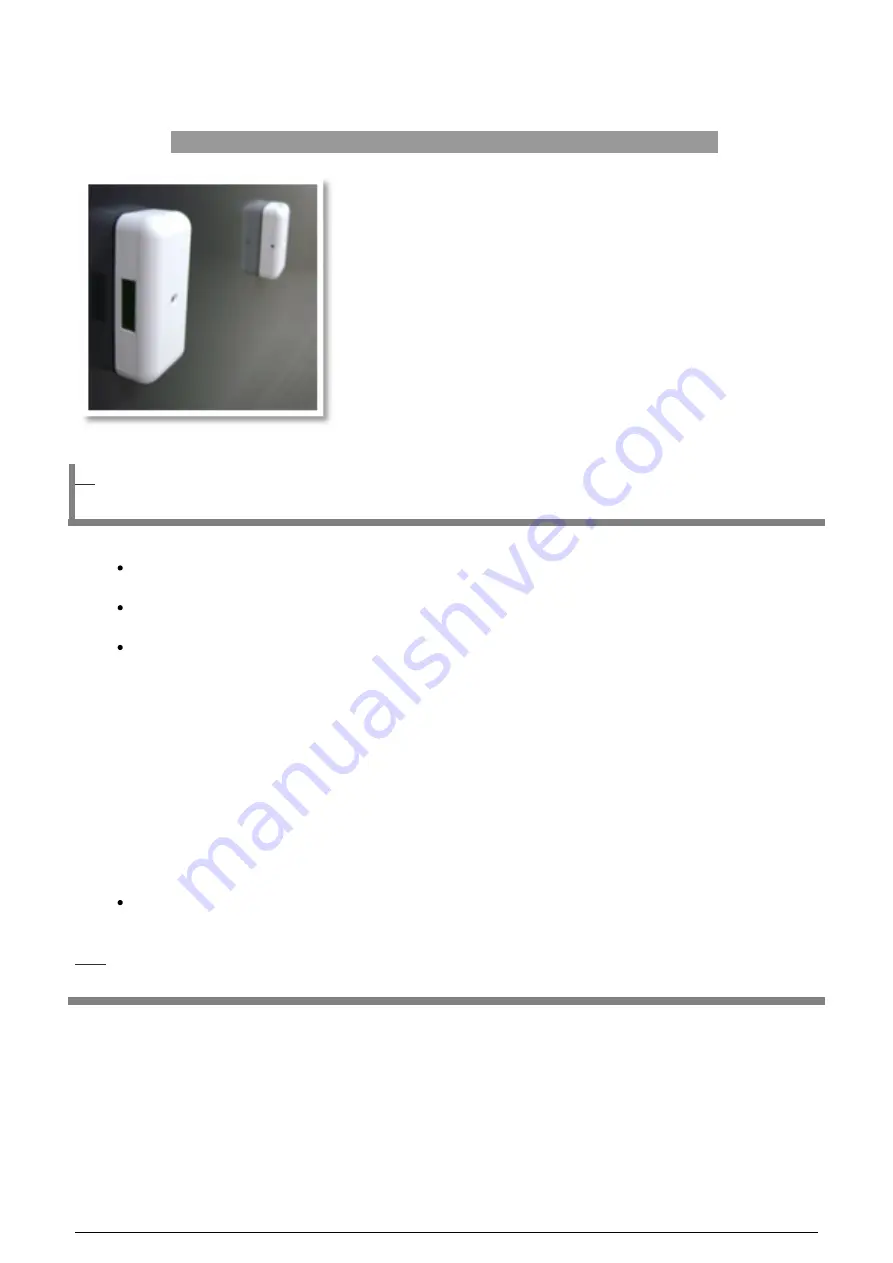
The PC-TB12N-W is a complete, self-contained, battery-operated people counter with an integral WiFi-enabled 802.11b data transmitter. This system consists of a photoelectric IR beam transmitter and receiver, which can operate up to 30 ft apart in front- or side-firing modes. The

counter will increment as the invisible IR beam is broken, regardless of the direction of traffic. The selectable group-counting feature counts groups of people as one unit, instead of counting individuals. The receiver has an integrated six-digit LCD counter for stand-alone use. This counter provides an easily installed, comprehesive network solution for local and/or central data collection. 

Features

Battery or Plug-in, self-contained counter with 802.11b Wi-Fi data transmitter installs in minutes

Six digit LCD display indicates setup parameters, battery life, and counter value

USB Configurable Options Include:

o


Wireless Security & Network Options Include DHCP or Static IP, WEP or WPA2

o


Adjustable High/Low sensing range to extend battery life

o


Selectable group counting feature will count a group of people as one unit instead of counting individuals

o


Front-Firing (Opposing Wall mount) or Side-Firing (Door-Frame Mount) in one unit

Use a PC-SSRX485 Sensor Server for easy data retrieval and system monitoring at corporate and/or store level.

Ordering P/N


PC-TB12N-W 

(with light grey enclosure, 

shown above

)


PC-TB12N-WB 

(with black enclosure)


 1 / 11

Summary of Contents for PC-TB12N-W

Page 1: ...installed comprehesive network solution for local and or central data collection Features Battery or Plug in self contained counter with 802 11b Wi Fi data transmitter installs in minutes Six digit LC...

Page 2: ...t expressly approved by SenSoure will void the warranty Cleaning Harsh cleaners such as paint remover or benzene may ruin the surface Use a soft wet cloth and mild soap or detergent to clean displays...

Page 3: ...the installation pop up window Follow the prompts to complete software installation 6 Proceed to the initial configuration of the units before launching the WiFi Sensor Utility program RX and TX Sens...

Page 4: ...PC 3 Use the small blue screwdriver to activate the Service Button by gently pushing on it once The LCD display will read CONFIG to confirm that the unit is now in Configuration Mode and ready to be s...

Page 5: ...name Enter the IP address for the Sensor Server that will be collecting data Destination Port Enter the port used by the Sensor Server to receive UPD packets If you have not changed the default settin...

Page 6: ...settings from the sensor Click the Reboot button to reboot the sensor The Tools Tab Provides simple troubleshooting tools for the RX unit Ping From Sensor or Ping From This PC to test whether the IP c...

Page 7: ...life approximately 1 2 years Low Allows a separation between the RX and TX units of up to 12 feet providing maximum battery life 1 7 years Hardware Installation Sensor Mounting Overview The sensors m...

Page 8: ...oor handling door swing must be taken into consideration before mounting the sensors especially true for Side Firing mode where sensors are typically mounted on the doorframe Ensure that the door does...

Page 9: ...ap the senor onto the back plate Note To remove the sensor from the back plate use the small blue screwdriver to push on the locking tab in the small hole at point C while pulling slightly on the sens...

Page 10: ...the Sensor Server Clearing the LCD Counter The counter may be reset by activating the Service button until the counter indicates a zero count approximately 4 seconds Reset Battery Meter If battery lif...

Page 11: ...battery meter is reset by activating the service button until the LED stays on approximately 8 seconds Configuration Mode The TX unit must be placed in configuration mode to change settings with the...

Reviews: