Seg MRD1-G, Manual
The Seg MRD1-G user manual is essential for unlocking the full potential of this sleek and powerful device. Easily download this comprehensive manual for free from our website to ensure seamless setup, operation, and troubleshooting. Enhance your Seg MRD1-G experience with this detailed guide, available exclusively at manualshive.com.
Share
Download


Reviews:
No comments
Related manuals for MRD1-G

LFP LiFePO4
Brand: Avon Pages: 2

Screen Protector for Fitbit Sense 2
Brand: Wasserstein Pages: 8

PL-H403W
Brand: Samsung Pages: 10

SP50L6HD
Brand: Samsung Pages: 84

SP403JHAX
Brand: Samsung Pages: 68

SP50L6HN
Brand: Samsung Pages: 96

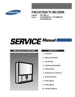
PCJ532RF
Brand: Samsung Pages: 59

SP50L7HD
Brand: Samsung Pages: 104

PLK403W
Brand: Samsung Pages: 64

PCJ522RX/XAA
Brand: Samsung Pages: 73

SP47W3HFX/BOB
Brand: Samsung Pages: 118

PLK405WX/XAC
Brand: Samsung Pages: 101

SP43T6HF1X/BWT
Brand: Samsung Pages: 134
PCJ522R
Brand: Samsung Pages: 134
SP-54T8HL
Brand: Samsung Pages: 56

SP403JHPX
Brand: Samsung Pages: 74

SP54R1HL1X/SHI
Brand: Samsung Pages: 102

PLK435W
Brand: Samsung Pages: 64


