18-35MM DIAL BORE GAUGE
MODEL NO:
DBG508.V2
Thank you for purchasing a Sealey product. Manufactured to a high standard, this product will, if used according to these
instructions, and properly maintained, give you years of trouble free performance.
IMPORTANT:
PLEASE READ THESE INSTRUCTIONS CAREFULLY. NOTE THE SAFE OPERATIONAL REQUIREMENTS, WARNINGS & CAUTIONS. USE
THE PRODUCT CORRECTLY AND WITH CARE FOR THE PURPOSE FOR WHICH IT IS INTENDED. FAILURE TO DO SO MAY CAUSE DAMAGE AND/OR
PERSONAL INJURY AND WILL INVALIDATE THE WARRANTY. KEEP THESE INSTRUCTIONS SAFE FOR FUTURE USE.
DBG508.V2 Issue 1 23/03/21
Original Language Version
© Jack Sealey Limited
Refer to
instructions
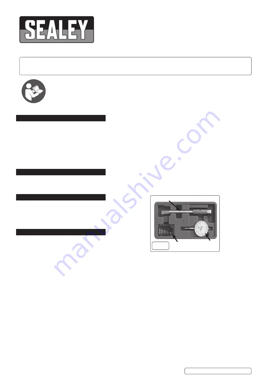
fig.1
Probe Body
1. SAFETY
WARNING!
Ensure Health and Safety, local authority and general workshop practice regulations are adhered to when using
tools and equipment.
8
DO NOT
use the dial bore gauge if damaged.
8
DO NOT
drop.
8
This is a precision instrument, always return gauge components to the internally lined storage case.
9
Maintain the gauge in good and clean condition for best and safest performance.
9
Keep the work area clean, uncluttered and ensure there is adequate lighting.
9
Ensure the work area floor is not slippery; wear non slip shoes.
9
Components to be measured and the dial bore gauge to be stored at room temperature (21°C).
2. INTRODUCTION
Precision mechanism with Ø58mm dial and locking rotating bezel, offering an accurate method of measuring a bore or detecting a
taper or ovality. Will indicate the deviation from set size by up to 10mm with an accuracy of 0.01mm. Probe body,
dial indicator, anvils and spacer rings are also included. Supplied in storage case.
3. SPECIFICATION
Model No: ............................................................. DBG508.V2
M
easuring Range:
..................................................... 18-35mm
M
aximum Deviation Measurement with Stem:
..................1mm
M
aximum Deviation Measurement Gauge:
.....................10mm
Resolution: ...................................................
0.01mm (0.0004”)
4. OPERATION
4.1.
SETTING UP
NOTE:
The dial ball gauge is a comparator not a measuring tool.
4.1.1.
Measure the bore diameter or gap to be measured to the nearest
millimetre with a rule or vernier callipers. The bore or gap must range between 18mm and 34mm nominally with this tool.
4.1.2.
Select the required anvil and locking ring. Thread the anvil into the threaded hole (fig.1) and lock in place using the locking ring such
that travel of the gauge probe is not inhibited.
4.1.3.
Assemble the dial bore gauge with selected parts as shown in fig.2. Ensure all components are clean before using.
4.1.4.
Insert the dial stylus into the probe body. The stylus will meet with resistance internally and the dial pointer will begin to rotate
clockwise. One complete cycle of the pointer is recommended for registration and will be indicated by the secondary dial indicator
(annotated 1-9). The small pointer should now be indicating “1” [one].
4.1.5.
Clamp the dial stem in place with the thumb screw.
DO NOT
over-tighten.
4.2.
Place the bore gauge in a micrometer locked to the same diameter of the hole being measured.
4.3.
After that, rotate the indicator’s dial until the pointer aligns with the “0” marking on the dial face.
Once this is done, insert the dial bore gauge in the bore, ensuring both anvils of the gauge touch the wall. Gently move the
bore gauge back and forth while keeping the anvils along the same axis plane. The pointer will swing either clockwise or
counter-clockwise as the anvils settle into place square to the bore.
4.4.
Once the tool is squared, watch the dial face. At some point, the pointer will start to reverse itself and head in the opposite direction.
This could be on either side of the “0” marking of the indicator. Record the measurement where the pointer reverses itself and
remove the bore gauge from the hole.
4.5.
Once you have removed the bore gauge from hole add or subtract the recorded value from the target number the indicator was
calibrated to. If the bore gauges indicator was zeroed to 32mm, and the pointer changed direction at the 0.07mm
marking on the dial face, the final measurement of the hole is 32.07mm. Alternatively, if the pointer travelled counter-clockwise
and changed 0.07 inches to the left of the “0” on the indicator, the final measurement of the hole is 32.93mm.
This is how you can read a dial bore gauge. Taking the correct reading is very important as one wrong reading can lead to incorrect
calculations, thereby diverting you from the basic motive of using a bore gauge.
A
nvils/Locking
R
ing
D
ial Gauge