Zenair CH 601 XL ZODIAC 2002, Flight Manual
The Zenair CH 601 XL ZODIAC 2002 is a sleek and efficient aircraft perfect for amateur builders and pilots. Ensure safe and enjoyable flights with the comprehensive Flight Manual available for free download from manualshive.com. This manual provides all the necessary information for a smooth and successful flying experience.
Share
Download


Reviews:
No comments
Related manuals for CH 601 XL ZODIAC 2002

5525
Brand: Laser Pages: 2

pss 3000
Brand: Mafell Pages: 75

LNF 20
Brand: Mafell Pages: 46

MT55 18M bl
Brand: Mafell Pages: 85

BS 60-2i
Brand: Wacker Neuson Pages: 42

CARLYLE TOOLS 6-1050A
Brand: Napa Pages: 16

CV-E
Brand: jbc Pages: 72

90.38 CLD2-5
Brand: Omer Pages: 2

HURST eDRAULIC SC 258 E2
Brand: Idex Pages: 44

ENESKAsonic
Brand: joke Pages: 12
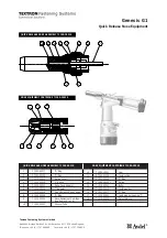
Textron Genesis G1
Brand: Avdel Pages: 2

FMT 250QSL
Brand: Fein Pages: 31

U78012-00
Brand: KRAUSMANN Pages: 20

PBSG 1
Brand: Parkside Pages: 51

D00803
Brand: Duratool Pages: 2

Buggy 10
Brand: Hamach Pages: 24

Katapult 11063
Brand: Klein Tools Pages: 1

TDS-13
Brand: TSO Products Pages: 2


