background image

INTRODUCTION

To the owner or user: The service manual you are
reading is intended to provide you, and the
maintenance or service technician, with the
information needed to install, start up, clean,
maintain, and service this ice system.

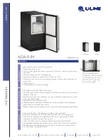
The NME1250 features: front service for the
evaporator, gearmotor, control box, water reservoir
and bin control; electronic circuitry for monitoring
ice and water level; a thermostatic expansion
valve; and HP62 as the refrigerant.

TABLE OF CONTENTS

FOR THE INSTALLER  .  .  .  .  .  .  .  .  .  .  .  .  .  .  .  .  .  .  .  .  .  .  .  .  .  .  .  .  .  .  .  .  .  .  .  .  .  .  .  .  .  .  . 2

FOR THE INSTALLER: Environmental Limitations .  .  .  .  .  .  .  .  .  .  .  .  .  .  .  .  .  .  .  .  .  .  .  .  .  .  .  .  . 3

FOR THE PLUMBER  .  .  .  .  .  .  .  .  .  .  .  .  .  .  .  .  .  .  .  .  .  .  .  .  .  .  .  .  .  .  .  .  .  .  .  .  .  .  .  .  .  .  .  . 5

FOR THE ELECTRICIAN  .  .  .  .  .  .  .  .  .  .  .  .  .  .  .  .  .  .  .  .  .  .  .  .  .  .  .  .  .  .  .  .  .  .  .  .  .  .  .  .  .  . 6

FOR THE INSTALLER: Final Check List  .  .  .  .  .  .  .  .  .  .  .  .  .  .  .  .  .  .  .  .  .  .  .  .  .  .  .  .  .  .  .  .  .  . 7

START UP  .  .  .  .  .  .  .  .  .  .  .  .  .  .  .  .  .  .  .  .  .  .  .  .  .  .  .  .  .  .  .  .  .  .  .  .  .  .  .  .  .  .  .  .  .  .  .  .  . 8

COMPONENT DESCRIPTION  .  .  .  .  .  .  .  .  .  .  .  .  .  .  .  .  .  .  .  .  .  .  .  .  .  .  .  .  .  .  .  .  .  .  .  .  .  .  . 9

ELECTRICAL SEQUENCE  .  .  .  .  .  .  .  .  .  .  .  .  .  .  .  .  .  .  .  .  .  .  .  .  .  .  .  .  .  .  .  .  .  .  .  .  .  .  .  .  . 12

OPERATION  .  .  .  .  .  .  .  .  .  .  .  .  .  .  .  .  .  .  .  .  .  .  .  .  .  .  .  .  .  .  .  .  .  .  .  .  .  .  .  .  .  .  .  .  .  .  .  . 13

CLEANING  .  .  .  .  .  .  .  .  .  .  .  .  .  .  .  .  .  .  .  .  .  .  .  .  .  .  .  .  .  .  .  .  .  .  .  .  .  .  .  .  .  .  .  .  .  .  .  .  . 15

MAINTENANCE: Auger  .  .  .  .  .  .  .  .  .  .  .  .  .  .  .  .  .  .  .  .  .  .  .  .  .  .  .  .  .  .  .  .  .  .  .  .  .  .  .  .  .  .  . 17

SERVICE DIAGNOSIS: Condition - No Ice Being Produced  .  .  .  .  .  .  .  .  .  .  .  .  .  .  .  .  .  .  .  .  .  .  .  . 18

SERVICE DIAGNOSIS: Condition - Low Ice Production  .  .  .  .  .  .  .  .  .  .  .  .  .  .  .  .  .  .  .  .  .  .  .  .  .  . 21

REMOVAL AND REPLACEMENT: Water Reservoir & Bin Control  .  .  .  .  .  .  .  .  .  .  .  .  .  .  .  .  .  .  .  . 22

REMOVAL AND REPLACEMENT: Bearing And Breaker  .  .  .  .  .  .  .  .  .  .  .  .  .  .  .  .  .  .  .  .  .  .  .  .  . 23

REMOVAL AND REPLACEMENT: Auger  .  .  .  .  .  .  .  .  .  .  .  .  .  .  .  .  .  .  .  .  .  .  .  .  .  .  .  .  .  .  .  .  . 24

REMOVAL AND REPLACEMENT: Water Seal  .  .  .  .  .  .  .  .  .  .  .  .  .  .  .  .  .  .  .  .  .  .  .  .  .  .  .  .  .  . 25

REMOVAL AND REPLACEMENT: Evaporator  .  .  .  .  .  .  .  .  .  .  .  .  .  .  .  .  .  .  .  .  .  .  .  .  .  .  .  .  .  . 26

REMOVAL AND REPLACEMENT: Gearmotor  .  .  .  .  .  .  .  .  .  .  .  .  .  .  .  .  .  .  .  .  .  .  .  .  .  .  .  .  .  .  . 27

REFRIGERATION SERVICE: HP62  .  .  .  .  .  .  .  .  .  .  .  .  .  .  .  .  .  .  .  .  .  .  .  .  .  .  .  .  .  .  .  .  .  .  .  . 28

CIRCUIT BOARD TESTING  .  .  .  .  .  .  .  .  .  .  .  .  .  .  .  .  .  .  .  .  .  .  .  .  .  .  .  .  .  .  .  .  .  .  .  .  .  .  .  . 30

Parts Lists and Wiring Diagrams are located in the center of this manual, printed on yellow paper.

This manual was printed on recycled paper.
Keep it for future reference.

Note this symbol when it appears.

It marks a potential hazard.

NME1250

August 1993

Page 1

Summary of Contents for NME1250

Page 1: ...ALLER Final Check List 7 START UP 8 COMPONENT DESCRIPTION 9 ELECTRICAL SEQUENCE 12 OPERATION 13 CLEANING 15 MAINTENANCE Auger 17 SERVICE DIAGNOSIS Condition No Ice Being Produced 18 SERVICE DIAGNOSIS Condition Low Ice Production 21 REMOVAL AND REPLACEMENT Water Reservoir Bin Control 22 REMOVAL AND REPLACEMENT Bearing And Breaker 23 REMOVAL AND REPLACEMENT Auger 24 REMOVAL AND REPLACEMENT Water Sea...

Page 2: ...KHQ LQVWDOOLQJ D QHZ V VWHP FKHFN WR EH VXUH WKDW RX KDYH HYHU WKLQJ RX QHHG EHIRUH EHJLQQLQJ RUUHFW LQ RUUHFW FH 0DFKLQH RUUHFW LQ 7RS LI UHTXLUHG OO NLWV OHJV DQG LQIRUPDWLRQ UHTXLUHG IRU WKH VSHFLILF MRE 63 7 216 0 5 0RGHO 1XPEHU DELQHW LPHQVLRQV DVLF OHFWULFDO RQGHQVHU 7 SH 5HIULJHUDQW KDUJH 5 0LQLPXP LUFXLW PSDFLW 0D LPXP XVH 6L H 10 LU RROHG RXQFHV 10 DWHU RROHG RXQFHV 0LQLPXP LUFXLW PSDFLW ...

Page 3: ...n ability and function Install one that filters out suspended solids to a dimension of 5 microns or smaller The finer the filter the better but finer filters will clog sooner than course ones It may be necessary to add a course filter ahead of the fine filter to prolong filter life 2 Check with a water treatment specialist for a water test and recommendations regarding filters and treatment Scotsm...

Page 4: ...les in the bottom of the bin Turn the leg levelers all the way in preparation for leveling later Return the bin to the upright position remove paper covering the bin gasket Install bin top if required Note Do not push bin into position but lift it there Pushing a bin especially one with ice in it can cause damage to the legs and the leg mounts Ice Maker The machine is heavy so the use of a mechani...

Page 5: ...he back of the cabinet the drain line is of the gravity type and 1 4 inch per foot fall is an acceptable pitch for the drain tubing There should be a vent at the highest point of the drain line and the ideal drain receptacle would be a trapped and vented floor drain Water Cooled Models In addition to the above mentioned drain a separate condenser drain must be installed Connect it to the 1 2 conde...

Page 6: ...uires a solid chassis to earth ground wire The ice maker should be connected to its own electrical circuit so it would be individually fused Voltage variation must remain within design limitations even under starting conditions All external wiring must conform to national state and local electrical codes The use of a licensed electrician is required to perform the electrical installation THIS UNIT...

Page 7: ...s been made and checked for leaks 4 Has the machine and bin been leveled 5 Is there a minimum of 6 clearance at the rear left and right of the machine for proper service access and air circulation 6 Is the water pressure a minimum of 20 psig 7 Has the machine been secured to the bin 8 Is there a water shut off valve installed near the machine 9 Have the shipping blocks been removed from under the ...

Page 8: ...led models the water regulating valve will open and warm water will be discharged into the drain 5 The unit should soon be making ice if desired the low side pressure can be checked it should be between 30 and 32 psig Low side pressure may be lower than 30 PSIG when the ambient is under 70o F and higher than 32 when ambient is over 90o F The suction line temperature at the compressor is normally v...

Page 9: ... out of Will shut the machine off it there is none Ice Discharge Chute Directs the ice made by the evaporator into the storage bin Ice Level Sensor An electronic eye it senses the presence of ice in the bottom of the ice discharge chute Operates to turn the ice machine on and off automatically as the level of ice in the bin changes Gear Motor An oil filled speed reduction gearbox driving the auger...

Page 10: ...me delay to clear the evaporator of ice when the unit turns off and for the compressor Transformer Supplies low voltage to the circuit board Low Pressure Control Cut Out A manual reset control to shut off the ice machine when the low side pressure drops below a preset point 0 4 psig Potential Relay The compressor start relay On Off Switch Manual control for the machine LOW PRESSURE CUT OUT ON OFF ...

Page 11: ...two seal faces meet Ice Sweep A plastic cap with fingers It revolves with the auger to sweep the ice into the ice chute Breaker Where the ice is compressed and much of the extra water is squeezed out of it before it is discharged into the bin Motor A split phase motor that drives the gear reducer Bearing As the ice is pushed up the evaporator the auger is thrust down and pressure from the auger th...

Page 12: ...e bin empty light goes out and the machine shuts down Shut Down consists of The compressor relay opens The compressor contactor opens The compressor stops The auger motor is run by the circuit board for 2 more minutes clearing out ice in the evaporator and then The auger motor relay opens and the auger motor stops If the ice level sensor is clear bin empty for more than 15 seconds the machine will...

Page 13: ...water circuit for the cooling water it enters the fitting at the rear goes to the water regulating valve then to the water cooled condenser and then down the drain WATER SCHEMATIC RESERVOIR STRAINER DRAIN EVAPORATOR DRAIN EVAPORATOR ICE CHUTE WATER LEVEL Note The water level may be checked by comparing the level of water in the reservoir to the line molded into the side of the reservoir The water ...

Page 14: ... depending upon the temperature of the evaporator warmer evaporators get more refrigerant and colder evaporators get less At the evaporator the refrigerant enters an area of relatively low pressure where it can easily boil off or evaporate As it evaporates it absorbs heat from the evaporator and whatever is in contact with it such as the water inside it After the evaporator the refrigerant now a l...

Page 15: ...e cleaning solution into the water reservoir until it is full Wait 15 minutes then switch the master switch to ON 9 As the ice maker begins to use water from the reservoir continue to add more cleaning solution to maintain a full reservoir 10 After all of the cleaning solution has been added to the reservoir and the reservoir is nearly empty switch the master switch to OFF 11 After draining the re...

Page 16: ...uld also be checked at least two times per year Check the bearing by removing the ice chute cover unscrewing the ice sweep removing the water shed unscrewing the breaker cover unscrewing the auger stud Inspect the assembly looking for wear See Removal and Replacement to replace bearing or seals Reverse to reassemble 4 Clean or replace the air cooled condenser filter Clean the air cooled condenser ...

Page 17: ...ep 4 Remove ice chute from evaporator 5 Remove 4 allen head screws holding breaker to evaporator 6 Pull up on breaker to remove auger Allow the auger to dry the stainless steel of the auger and evaporator must be clean and bright Clean the auger and evaporator as required DO NOT HONE THE EVAPORATOR 7 Replace the water seal 8 Reverse to reassemble Air Cooled Models Clean the Air Filter and Condense...

Page 18: ...ck for a Thermostatic Expansion Valve that does not open if defective replace it Replace the drier evacuate and weigh in the nameplate charge E Check the high pressure cut out if closed go to F if open check 1 The pressure control opens at 450 psig Check the high side pressure reset the control and observe on water cooled that water soon begins to flow from the condenser drain or on air cooled tha...

Page 19: ...n full light on the tester should be ON if not replace the circuit board If the bin full light on the tester is ON move the tester switch to bin empty the light on the tester should go OFF and the bin empty light on the circuit board should go ON If not replace the circuit board If it does as above and the machine still does not run replace the ice level sensors 3 If the transformer is fine and th...

Page 20: ...l is open replace the contactor 3 Check the auger drive motor centrifugal switch If when the drive motor is running contact 4 black wire removed has no power and all of the above switches have been checked replace the centrifugal switch or the drive motor 4 If the compressor relay on the circuit board has power on the NO contact but not on the COM contact replace the circuit board B Check the comp...

Page 21: ...ace the water seal if found to be leaking 3 Check the low side pressure normal is about 30 32 psig If low assume a refrigerant leak locate repair and recharge If no leak the TXV may be restricted defective or not adjusted properly If needed replace the TXV evacuate and recharge per nameplate 4 Check the insulation on the evaporator It should be dry with no wet spots or frost If the insulation has ...

Page 22: ...ir from icemaker 8 Reverse to reassemble BIN CONTROLS Ice Level Sensors 1 Disconnect electrical power 2 Remove front panel 3 Remove control box cover 4 Locate ice chute at the base of the chute in front of and behind it are two plastic bin control mounts 5 Slide each bin control to the left and in the control box disconnect the electrical leads connecting the bin control to the circuit board 6 Rev...

Page 23: ...bearing Check for rust rough spots and damage a The bearing is pressed into the breaker to remove the bearing and replace it an arbor press is needed b Replace lower seals before installing new bearing in breaker Note seals must be pressed in with a tool pushing against the outer edge only they will not install by hand Replace parts as required Re grease bearing with Scotsman part no A29123 001 be...

Page 24: ...ding breaker to evaporator d Lift up and remove breaker from evaporator e If the auger is stuck use a slide hammer type puller to pull on the auger at the threaded hole The size of that hole is 5 8 18 Inspect the auger the critical areas of the auger are 1 The auger body It should be clean and shining Sometimes an auger will appear clean when wet but after it is dry it will be seen to be stained S...

Page 25: ... and pull the water seal down against it 3 The part of the water seal that rotates with the auger must also be replaced Remove the old part from the auger and clean the mounting area 4 Place a small bead of food grade silastic sealant such as 732 RTV or Scotsman part number 19 0529 01 on the area of the auger where the water seal is to be mounted 5 Carefully push the water seal rubber side against...

Page 26: ...until dehydrated then weigh in the nameplate charge Check for leaks 8 Install auger breaker breaker bearing assembly and ice discharge chute in reverse order of disassembly See To Reassemble Evaporator and Auger To Reassemble the Evaporator and Auger 1 After the gearmotor has been inspected fasten the evaporator to the gear motor be sure that the number of shims indicated on the gear case cover is...

Page 27: ...If there is evidence of water in the oil rusty bearings and gears the oil having a creamy white appearance oil level too high carefully inspect the bearings and gears If in doubt about the condition of a part replace it The oil quantity is 14 fluid ounces do not overfill Note The gears and bearings are available only as pressed together sets D After replacing parts as required if any reassemble th...

Page 28: ... manufacturer if in doubt As with any other refrigerant do NOT mix HP62 with pressurized air when leak testing Pressure Temperature Chart for HP62 VAPOR VAPOR TEMP PRESSURE TEMP PRESSURE DEG F PSIG DEG F PSIG 20 17 70 146 18 18 72 150 16 20 74 155 14 21 76 161 12 23 78 166 10 24 80 171 8 26 82 177 6 28 84 182 4 29 86 188 2 31 88 194 0 33 90 200 2 35 92 206 4 37 94 212 6 39 96 219 8 41 98 225 10 43...

Page 29: ...repaired This system has a critical charge it must be recharged with the correct amount of refrigerant as listed on the nameplate of the ice machine or performance will suffer Anytime the refrigeration system has been opened the dryer should be replaced Note Only a HFC type dryer should be used When brazing the tubing connections to components such as the TXV the component must be protected by hea...

Page 30: ...from the circuit board 2 Plug photo trans and LED connectors from the tester into the circuit board a Move the bin full switch on the tester to Full The light on the tester should be ON If the light on the tester is not on the circuit board should be replaced b If the light on the tester IS on move the bin full switch to Bin Empty The light on the tester should go OFF and the Bin Empty light on th...

Page 31: ...ot replace the circuit board b Move the water switch on the tester to the Water position The No Water light on the board should go OFF If not replace the circuit board If the light does go off replace the water level sensor If the Bin Empty light is ON wait 10 20 seconds for the machine to start The machine should start CIRCUIT BOARD TESTING WATER SENS LIGHT ON SWITCH TO NO WATER LIGHT OFF SWITCH ...

Reviews: