Schloder SESD 200, Operation Manual
The Schloder SESD 200 Operation Manual is available for free download on our website. This comprehensive manual provides detailed instructions and step-by-step guidance on utilizing the product's features efficiently. Access the user manual now on manualshive.com, and make the most of your Schloder SESD 200 experience.
Share
Download


Reviews:
No comments
Related manuals for SESD 200

026049
Brand: GYS Pages: 48

BATTERY RECHARGER
Brand: Igo Pages: 2

RRP-433
Brand: Railroad Products Pages: 2

90-620
Brand: Napa Pages: 32

QLH-WCH-1800
Brand: QUAD Pages: 4

UNI 3AS
Brand: Hama Pages: 2

EVA-07S-PE-RFID
Brand: Project EV Pages: 68

YT-8304
Brand: YATO Pages: 32

OE 2040
Brand: CLAS Pages: 16

45.137.55
Brand: EINHELL Pages: 8

XEV427
Brand: hager Pages: 4

K8500
Brand: Kodak Pages: 1

FLEXPOWER
Brand: Master-force Pages: 16

X7 Signature
Brand: CHARGEHUB Pages: 34

INFINEA BLUEPAD
Brand: Infinite Peripherals Pages: 47

Nuron C 6-22
Brand: Hilti Pages: 376

HU6525
Brand: Hulk Pages: 28
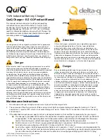
QuiQ
Brand: Delta-q Pages: 2


