Sapling SAM Series, Installation Manual
The SamplexPower SAM Series is a cutting-edge product designed to revolutionize your audio experience. To fully maximize its capabilities, it is essential to refer to the comprehensive Owner's Manual. Download this manual for free from our website to unlock the product's full potential and elevate your audio game.
Share
Download


Reviews:
No comments
Related manuals for SAM Series
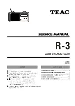
R-3
Brand: Teac Pages: 17

CR-213
Brand: Denver Pages: 14

SPYCCL10CSR
Brand: nedis Pages: 176

MRC 4150
Brand: AEG Pages: 86

MR 4115i
Brand: AEG Pages: 58

MRC 4119 P N
Brand: AEG Pages: 114

MRC 4132 BT
Brand: AEG Pages: 66

MRC 4136
Brand: AEG Pages: 78

MRC 4147 L
Brand: AEG Pages: 46

FU 4002 P
Brand: AEG Pages: 98

MRC 4121
Brand: AEG Pages: 126

MRC 4137
Brand: AEG Pages: 86

MRC 4159 P
Brand: AEG Pages: 98

MRC 4126 P
Brand: AEG Pages: 86
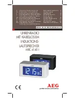
MRC 41401
Brand: AEG Pages: 166

MRC 4105 P
Brand: AEG Pages: 86
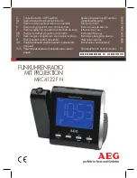
MRC 4122 F N
Brand: AEG Pages: 126

MRC 4151
Brand: AEG Pages: 42


