SERVICE MANUAL
Contents
1. OUTLINE OF CIRCUIT DESCRIPTION ............................... 3
2. DISASSEMBLY ................................................................... 12
3. ELECTRICAL ADJUSTMENT ............................................. 21
4. USB STORAGE INFORMATION REGISTRATION ............ 25
5. TROUBLESHOOTING GUIDE ............................................ 26
6. PARTS LIST ........................................................................ 28
CIRCUIT DIAGRAMS & PRINTED WIRING BOARDS ........... C1
CAUTION : Danger of explosion if battery is incorrectly replaced.
Replace only with the same or equivalent type recommended by the
manufacturer.
Discard used batteries according to the manufacturer’s instructions.
NOTE : 1. Parts order must contain model number, part number, and description.
2. Substitute parts may be supplied as the service parts.
3. N. S. P. : Not available as service parts.
Design and specification are subject to change without notice.
SG114/U, EX, GX, EX2, EX3, U2, U3 (R)
REFERENCE No. SM5310711
FILE NO.
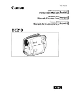
Digital Movie Camera
VPC-E1W
(Product Code : 168 094 01)
(U.S.A.) (Canada)
VPC-CA65EXW
(Product Code : 168 094 02)
(Europe) (U.K.) (South America)
(China) (Australia) (Hong Kong)
(Russia) (Middle East) (Africa)
(General) (Korea) (Taiwan)
RoHS
•
This product does not contain any hazardous substances prohibited by the RoHS
Directive.
WARNING
•
You are requested to use RoHS compliant parts for maintenance or repair.
•
You are requested to use lead-free solder.
(This product has been manufactured using lead-free solder. Be sure to follow the
warning given on page 2 when carrying out repair work.)
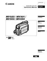
VPC-CA65GXW
(Product Code : 168 094 03)
(South America) (China)
(Australia) (Hong Kong)
(General) (Korea) (Taiwan)
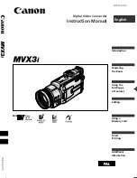
VPC-CA65EXBL
(Product Code : 168 094 05)
(Europe) (U.K.) (South America)
(China) (Australia) (Hong Kong)
(Russia) (Middle East) (Africa)
(General) (Korea) (Taiwan)
VPC-CA65EXYL
(Product Code : 168 094 07)
((Europe) (U.K.) (South America)
(China) (Australia) (Hong Kong)
(Russia) (Middle East) (Africa)
(General) (Korea) (Taiwan)
VPC-E1BL
(Product Code : 168 094 08)
(U.S.A.) (Canada)
VPC-E1YL
(Product Code : 168 094 09)
(U.S.A.) (Canada)