background image

Summary of Contents for SBM-201

Page 1: ...SERVICE MANUAL Automatic Bread Maker FILE NO SBM 201 PRODUCTIONCODENO 343631822 New Zealand 343631829 Malaysia REFERENCE NO SM 680078 ...

Page 2: ... Fuse Baking temp 157 C New Zealand Instruction manual Cook book Accessories Malaysia Insutuction manual measuring cup 2 Constructions and Operation 1 ConstructIons The kneader blade attached to the inner pot ass y is rotated by the main motor by way of the pulley and the belt The ingredients inside of the inner pot are kneaded by the kneader blade The inside of the temperature is controlled by th...

Page 3: ...i I Outline of Constructions I I I 1 I L k u w Hopperass y Blade d lr r 1 1 I I 1 r f I I f d d Sensor ass y Fuse ass y Motor I 2 ...

Page 4: ...stics important for safety When replacing any of these parts use only manufacturer s specified parts 1 I CJ L J t A I T I r m HAC102 J1 L l At 11 Q 4 kdi r T Ti a 0 s z 1 1 q 1 1 C s 1 1 5 0 1 C108 1 1 ii B 11 L F n g 1 0 a s Zol L N D 03 g C9 I YL_ l Il e D2 I II I m WC 1 0 3 ...

Page 5: ...xide Resistor 220t2 1W R102 RI 03 R108 I Metal Oxide Resistor 100 1 l 2W BZ101 Piezo BuzzerPKM17EPP 4001 PT101 Power Transformer T35 0240 CONTROL UNIT SYMBOL SPECIFICATION icl IC pPD75064CU 028 Q1 Transistor 2SC1740S or 2SC1570 Q2 Digi Tra DTC114ES Q3 Q4 Q5 Q6 Digi Tra DTA143ZS LD1 LEDA 3335H LD2 LED5133D D1 D2 D3 D4 D5 Diode 1SS131 ZD1 ZD2 Zener Diode RD12ESB2 or RD12ESB3 cl C3 Ceramic Cap 0 1pF ...

Page 6: ...DD I T T T I T l pi G T C106 Clul I bl I I I Vllul 1 D101 D1o4 L 1 I 1 t 1 f q Vss I I oltage at each point Ground is shown as Vss I I 13V 5V Description of operation 1 VDD VSS Power supply 5V The secondary output of power transformer PT101 is given bridge rectification by the diode D101 D104 and the condenser C107 to produce 13V voltage at The voltage at is used to compose 5V power supply by the ...

Page 7: ... 03 Photo triac PH101 and thentriac TAC101 to operate the heater 2 Motor control circuit When the voltage at pin 14 of the micro computer IC1 becomes Low OV the signal will drive transistor Q1 04 transistor Ql 02 Photo traiac PH1 02 and thentriac TAC102 to operate the motor 5 Control circuit for inner temperature Circuit diagram 2 VDD z 1 17 AN1 i G Ii i 25 P20 Icl 42 Vss Description of operation ...

Page 8: ...NEADFIRST PUNCH REST SHAPEFINAL BAKE 5 min 20min 50sec 10sec 25 min 16W 45 sec 60min J4 u4 T OFF OFF ON OFFOFF OfVOFFOFF OFJOFF ON OFF ON I ON OFF ON OFF ON 10 FF OFF I I I 1 1 1 ON ION ON ON ION ION ONION i KEEP WARM 2 Max 60 min ON DFF FF 2K E KEEP SettingKNEADKNEADFIRST PUNCH REST SHAPEFINAL BAKE WARM RISE DOWN RISE 2 10min 16min 29min Msx 11hre 5 min 20min 50sec loeec 8 min 10sec 50sec 40min 6...

Page 9: ...KNEAD KNEAD FIRST PUNCHREST SHAPE FINAL BAKE WARM 10min RISE DOWN RISE 2 Time until finish lOhrs 39min 49min Max of BAKE 7 min 5 min 13min 45 sec 15sec 15min 10sac 50 sec 50 min Ml min 2hrs 53 min 6 125 C 30 C 14 C L Heater ON OFF OFF OFF ON OFF OFF ONIOFF OFF ON OFF ON OFF ON OFF Main motor OFF ON ON OFF ON OFF ON OFF OFF OFF LED Operation ON ON ON ON ON ON ON ON ON ON OFF L 6 Quick KNEADKNEADKNE...

Page 10: ...et KEEP Setting KNEAD KNEAD FIRST PUNCHREST SHAPE FINAL BAKE WARM 10min RISE DOWN RiSE 2 Time untiifinish 9 hrs 39 min 49 min Ms of BAKE 35 min 5 min 20 min 50 sac 10See 25 min 5 sec 55 sec 65 min 60 min 3hrs 25 min 105 C 30 C 14 C Heater ON OFFOFF OFF ON OFFOFF ON OFFOFF ON OFF AON OFF ON OFF Mainmotor OFF N ON OFF ON OFF ON OFF OFF OFF LED OperstiGII ON ON ON ON ON ON ON ON ON ON OFF 9 Pizza Dou...

Page 11: ... 5 min Heater Mainmotor LEO Operation OFF OFF OFF I I ON ON ON I I ON ON ON REST KNEAD 1 min 5 min 14 min OFF OFF OFF ON ON ON I 1 During of the KNEAD process the main motor is operated intermittently 2 The KEEP WARM process is maximum 60 minutes Even if within 60 minutes when temperature of sensor is under 80 temperature impressed the keep warm is completed 10 ...

Page 12: ...s sounding input o To STOP 2 o To SELECT 3 x Keyinputis neglected Whileerror is sounding x Key input is neglected While error is sounding o To PASTA 9 2 STOP Basic OFF No indication WhenSTOP Operation switchis depressedin the condition 1 Operation x Key input is neglected against While error is sounding input o To STOP 2 o To SELECT 3 x Key input is neglected While error is sounding x Key input is...

Page 13: ...CT switch input To TIMER SEITING 4 o To TIMER SEITING 4 o To PASTA 9 4 TIMER Basic A UP 3 jOFF 310 is displayed SETTING Operation WhenA up or In case of Basic Normal w down switch is depressed in the condition A down 3 3 Operation o Starts according to timer setting against To START 6 input o To STOP 2 o Moves onto menu select 5 of timer setting o When pressed TIMER SET time increases in time is a...

Page 14: ...y To TIMER SET 5 To PASTA 9 Course change is not carried out Display time is counted up 10 minutes Displaytime is counted down 10 minutes o ON 6 START Basic Operation Displaybakingtime Operationstartsfor baking timeselectedby the SELECT keyor thePASTAkey Thecolon changesfrom beingsteadilylit to flashing andthe displayis counted down1 minuteat a time Whenthe START keyis pressed afterselectionor whe...

Page 15: ...Key input is neglected Key input is neglected Key input is neglected Key input is neglected The colon changesfrom flashingto beingsteadilylit Key input is neglected No error warning To STOP 2 Key input is neglected No error warning Key input is neglected No error warning Key input is neglected No error warning Key input is neglected No error warning Remarks Changesto Keepwarm modeafter bakingis co...

Page 16: ...d against input o To STOP 2 o To SELECT 3 o Indication is not changed o Indication is not changed o To PASTA 9 Demonstration for inspection Inspection demonstration mode is set when power plug is connected to the power outlet while depressing all of SELECT DOWN and START switches Operation is the same as ordina one Only exception is that depressing of UP key at the time of starting makes the proce...

Page 17: ...fitting screws of the terminal And removing the power cord ass y can be dismounted from the main unit by loosen the fasten screw of the cord bushing 5 The main unit can be pulled up after removing 6 fitting screws of inner cabinet U and the main unit and hinge can be separated out of cabinet Fig 2 The cord bushing can be dismounted by removing the net of the cord bushing from the cabinet 6 Cut the...

Page 18: ...ield can be removed by removing the 2 fitting screws of the shield 15 Pull out the 2 sockets of the lead wire from the heater By removing the heater supporting insulator 16 17 18 fitting nut and the insulator A fitting hook of inner cabinet M the heater ass y and insulator A can be dismounted from the inner cabinet Fig 5 By removing the fitting screw of the holder heater the holder heater and the ...

Page 19: ...1 When mounting the power cord the cord bushing should be attached to the cord holder so that the dimensions between the bushing and the top of the terminal is approx 25 mm Fig 6 2 Wiring should be made as shown in the specified wiring diagram Fig 6 Power PCB z Control PCB Black with socket qL Power PCB Motor Power PCB Blue and Yellow with socket flfl yea h B r 5 UI White with socket wL Fig 6 w 18...

Page 20: ...lt the motor fitting screws are temporary to fit in the first place Install tension of the belt become 13kg after the belt hangs on the pulley big Belt Ring C Holder Chassis and I Illustration of Wiring the the 1 Power PCB r Power cord LJ Capacitor ...

Page 21: ...8 Wiring Diagram for Repair nI v M TERMINAL Ac o alaysia AC 230V New Zealand OVER TEMPERATURE PROTECTOR 20 ...

Page 22: ... T T Y 1 I 21 ...

Page 23: ...al condition Approx DC 5V 1 Remove the power cord from the socket Wait 30 seconds and then turn the power on again Inspection e Normalized YES whenplug in YES e YES Normal voltageis N supplied b zs I Start 1 Normalized YES hen plug in I NO Cause Microcomputer went out of control due to external noise Poor connection of CN101 Poor connection of connector lead wire Thermal fuse failure Power board f...

Page 24: ...tor failure YES Poor connection of CNI03 Control board NO failure IYES t YES Sensor failure L Heater failure Heaterfailure YES Poor connection of CN102 NO NO Control board failure A Power board YES failure Countermeasure Replace motor Repair wiring Replace control board Replace power board Replace sensor Replace heater Repair wiring Replace control board Replace power board E Buzzer is not sounded...

Page 25: ...0kf3 thermister short E 04 YES inner case is Sensor failure Replace sensor abnormal high temperature E 08 inner case is high NO Control board Replace control temperature failure board more than 60 C when rising appears in display window 1 E 05 appears 1 Check if heater and in display heater wiring are in window Inner normal condition casetemperatu re is not go up Heater failure or Replace heater w...

Page 26: ...10 Exploded view The parts marked with A41 c o o b have special characteristics important for safety When replacing any of these parts use only manufacturer s specified parts 32 I 4 29 o 8 d 85 73 25 ...

Page 27: ...91 4 26 ...

Page 28: ...00937961 Ring AE 1 8416370093789 I Ring C 12 i QKI CQ7 fi n 8858 Screw flat I_rd 4X8mm 3 I raGim7 nf9 5114 Screw trues hd 4X8mm 2 1551 Washer spring 4mm 2 88 637 012 5107 Hexagon nut 4mm 2 89 637 010 8971 Screwr pan hd 3X 10mm 2 27 637 01 17370 Cap lSeal hoidino r iatei Ili 28 6370130996 Shaft 1 29 637 013 1016 Shaff umer 1 i I i I ti wz 1 ill n w ass v 30 16370088020 Gaskef Oil seai 1 31 16370093...

Page 29: ...ac 6370118871 TM561S L 2 TAC1O1 TAC1O2 LED 6370131344 A 3335H 1 LD 1 Metalized Film Cap 6370131351 CFJC22E104M X 2 C103 C109 Photo Triac 6370132389 MOC3021 2 PH101 PH102 Varistor 6370132396 VE09M02750K 1 VAR 1 Varistor 6370118956 MFCN08D431 K 1 VAR 2 power Transformer I 6370132402 I T35 0240 I 1 IPT101 28 ...

Page 30: ...Printed in Japan Sq41Mio SANYO Electric Co Ltd Osaka Japan ...
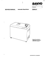
Reviews: