background image

Multimedia Projector

SERVICE MANUAL

Product code 

1 122 410 20

 (KT3AL)

1 122 411 20

 (LT3AL)

original Version

REFERENCE NO. 

SM

5110875-00

 FILE NO.

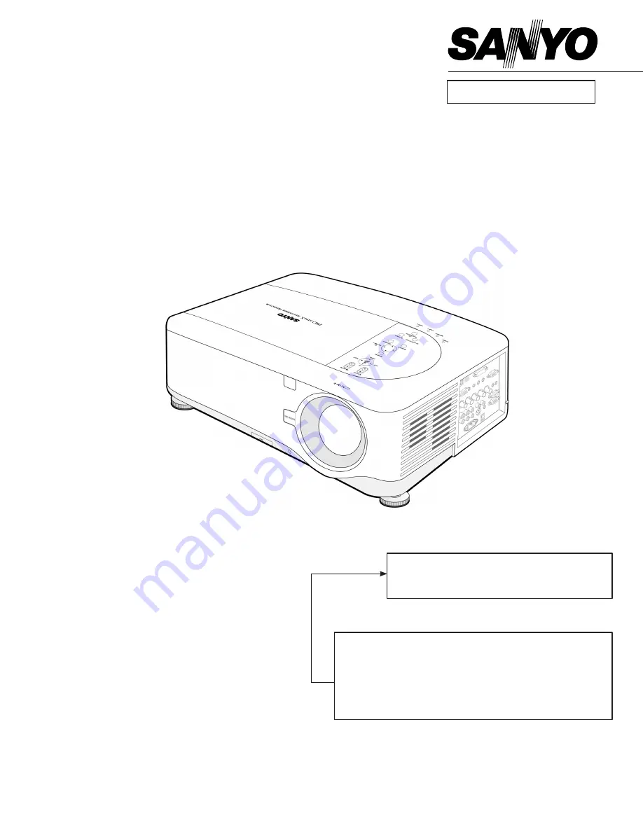
Model No.  PdG-dXt10L


U.S.A, Canada,  


Europe, U.K, Asia

chassis No.  Kt3-dXt10L00

Match the Chassis No. on the unit's back cover with the 
Chassis No. in the Service Manual.
 If the Original Version Service Manual Chassis No. does 
not  match  the  unit’s,  additional  Service  Literature  is  re-
quired. You must refer to “Notices” to the Original Service 
Manual prior to servicing the unit.

Summary of Contents for PDGDXT10L - XGA DLP Projector

Page 1: ... DXT10L U S A Canada Europe U K Asia Chassis No KT3 DXT10L00 Match the Chassis No on the unit s back cover with the Chassis No in the Service Manual If the Original Version Service Manual Chassis No does not match the unit s additional Service Literature is re quired You must refer to Notices to the Original Service Manual prior to servicing the unit ...

Page 2: ... ...

Page 3: ...0 2 8 Wire Location 12 3 TROUBLE SHOOTING 13 3 1 Operation check 13 3 2 Main Board check 14 3 3 LED State Indications 16 4 DISASSEMBLY AND ASSEMBLY 17 5 ADJUSTMENT 44 5 1 Step of Into Service mode 44 5 2 Calibrate VGA 1024 x 768 60Hz 45 5 3 Calibrate YUV 46 5 4 Calibrate Video 47 5 5 Color Wheel Index Adjustment 50 5 6 Focus Adjustment 52 6 SECURITY NOTICE 59 6 1 Preventing the Unauthorized Use of...

Page 4: ... Switch 65 7 5 Lamp Door Interlock Switch 66 8 Maintenance 67 8 1 Cleaning the projector 67 8 2 Replacing Consumable Parts 71 9 Factory Preset Display Modes 79 10 Required adjustments when the parts replaced 81 11 Spare part list 82 ...

Page 5: ...d wiring etc are returned to their original positions Tube tape and other insulation materials have been used for safety reasons The internal wiring has been designed to avoid direct contact with hot parts or parts under high voltage when using clamps or other tools 4 The parts used in this device have special safety features such as flame resistance and anti voltage properties When replacing part...

Page 6: ... 200 1 27m 5 08m LNS W41 40 500 1 02m 12 7m LNS W40 LNS S40 LNS T40 LNS T41 Lens options LNS W41 Power focus throw ratio 0 77 1 F2 0 f 11 4 mm LNS W40 Power zoom and focus throw ratio 1 33 1 79 1 F1 8 2 3 f 19 3 25 8 mm LNS S40 Power zoom and focus throw ratio 1 78 2 35 1 F1 7 1 9 f 26 34 mm LNS T40 Power zoom and focus throw ratio 2 22 4 43 1 F2 1 2 9 f 32 63 mm LNS T41 Power zoom and focus throw...

Page 7: ...3 PAL PAL 60 N M B G H I SECAM HDTV 1080i 720p SDTV 576p 576i 480p 480i Scan Rate Horizontal 15 kHz 31 to 90 kHz RGB 31 kHz or over Vertical 50 Hz to 85 Hz Video Bandwidth RGB 100 MHz 3dB Color Reproduction 16 7 million colors simultaneously Full color Horizontal Resolution NTSC NTSC4 43 PAL PAL M PAL N PAL60 540 TV lines SECAM 300 TV lines RGB 1024 dots H x 768 dots V External Control RS232 IR LA...

Page 8: ...n Operational Temperatures 41 to 104 F 5 to 40 C 10 to 90 humidity non condensing Storage Temperatures 14 to 140 F 10 to 60 C 5 to 90 humidity non condensing 2 5 Regulations UL C UL Approved UL 60950 1 CSA 60950 1 Meets FCC Class B requirements Meets DOC Canada Class B requirements Meets AS NZS CISPR 22 Class B Meets EMC Directive EN55022 EN55024 EN61000 3 2 EN61000 3 3 Meets Low Voltage Directive...

Page 9: ...PDG DXT10L 9 2 6 Block Diagram ...

Page 10: ...nt and matrix processing at the Scaler circuit and then converted into the RGB signals The RGB and VIDEO input signals are switched over at the selector After passing through the signal adjusting circuit of color space processing auto adjustment etc these signals are written in the RLDRAM The video signals called up from the RLDRAM pass through the definition converter circuit ON screen display er...

Page 11: ...he scaler U400 controls all of this system 2 7 6 Power circuit 6 1 Main power supply In the state of standby the power is supplied 5V to the scaler scaler peripheral ICs and FLASHROM After the power is ON the power at 2 5V 3 3V 5 7Vand 13V is fed to the analog circuit fan formatter board etc 6 2 Lamp power supply The lamp is lit with POWER ON Unlighting detection is performed 2 7 7 Safety design F...

Page 12: ...PDG DXT10L 12 2 8 Wire Location ...

Page 13: ...OTING 3 1 Operation check By making operation checks under normally operating conditions a certain degree of judgment is possible on errors Prior to the removal of the top cover check the POWER indicator and the STATUS indicator ...

Page 14: ...PDG DXT10L 14 3 2 Main Board check ...

Page 15: ...PDG DXT10L 15 CN110 CN109 ...

Page 16: ...ED 3 times BLINK repeatlly 0 5sON 0 5sOFF 3 2 0sOFF ERROR FAN ERROR RED 4 times BLINK repeatlly 0 5sON 0 5sOFF 4 2 0sOFF ERROR Keylocked when push key ORANGE light up ON Keylock function enable Idle GREEN ON ON Lamp LED Projector Status LED Condition LED Sequence Projector Condition Lamp Off BLANK OFF All Time End of the Lamp life RED BLINK 0 5sON 0 5sOFF All Time Lamp replace NO LAMP RED 1 time B...

Page 17: ...SSEMBLY Removing the Lamp Cover and Lamp Module Look the full set projector Look at the IO side Look at the keypad of top side Look at the keypad of top side D I S A S S E M B L Y Loose this one screw Remove and take out the lamp cover ...

Page 18: ...XT10L 18 Removing the Lamp Cover and Lamp Module Look at the top side Loose these four screws and take out Remove the lamp modules upward view Look the Lamp D I S A S S E M B L Y Look the Lamp Look the Lamp ...

Page 19: ...0L 19 Removing the Lamp Module and Top cover Look the Lamp Look the Lamp Remove the eight screws Look the screws D I S A S S E M B L Y Rotates around the bottom side and Remove the seven screws Look the screws ...

Page 20: ... DXT10L 20 Removing the Top cover Remove this way and take off Remove this way and take off Remove this way and take off Remove the top cover D I S A S S E M B L Y Remove the FFC cable from the keypad side ...

Page 21: ...rd and Removing the Top cover Shield Look the Keypad board and take off Remove the IR cover 1 Remove the IR cover 2 Remove the 16 piece screws D I S A S S E M B L Y Careful this area and check this place when you assemble this plate ...

Page 22: ...lace the color wheel Look at the 16 piece screws Remove the top cover shield Remove the four screws and take away Remove the three screws Check mount direction D I S A S S E M B L Y Remove the three screws and take this case away Review the color wheel ...

Page 23: ...nd Removing the Lens Review the color wheel Review the color wheel Color wheel module off Look at the Lens release bottom D I S A S S E M B L Y Push the Lens release bottom Turn anti Clockwise and pulled the lens away The Optical Lens review ...

Page 24: ... DXT10L 24 Removing the Lens cap Review the screw Review this screw Review the screws IR Ass y Remove the lens cap D I S A S S E M B L Y Careful and check this place when you assembled Review the lens cap ...

Page 25: ...DG DXT10L 25 Removing the Main Board Review these two screws Remove the lens ring Review the five screws cover shield Review these two screws I S A S S E M B L Y Review these two screws Review the screws ...

Page 26: ...PDG DXT10L 26 Removing the Main Board Review the Main Board Top side D I S A S S E M B L Y Review the Main Board Bottom side ...

Page 27: ...Review the projector Remove these four screws Review the screws Arrange the wires as picture when you assemble it D I S A S S E M B L Y Unplug these four hook buckles and careful the assembly Careful and check this place when you assembled ...

Page 28: ...over Lamp module Careful and check this place when you assembled Careful and check this place when you assembled Unplug and check this hook buckle Review the Lamp cover D I S A S S E M B L Y The Lamp cover off View the Fan module area ...

Page 29: ...amp module Take these two sets away Take these two fans away Care the fan wire assembly See the connector location D I S A S S E M B L Y Becareful the two side of arrow mark direction Becareful the two side of arrow mark direction ...

Page 30: ...ving the Lamp module Optical module Take these two sets away Remove the screw and Careful the hook buckle Remove these six screws Review the screws D I S A S S E M B L Y Review the screws Remove the Optical engine module ...

Page 31: ... Lens Shift motor module Careful and check this place when you assembled Careful and check this place when you assembled The Optical module off Remove these six screws D I S A S S E M B L Y Review the screws Remove the Lens Shift motor module ...

Page 32: ... Shift motor module off Careful and check this place when you assembled Careful and check this place when you assembled Careful and check this place when you assembled D I S A S S E M B L Y Remove these 8 screws and Careful the three place when you assembled Review the screws ...

Page 33: ...wer shield Back cover Careful and check this place when you assembled Careful and check this place when you assembled Review the Power Shield Top side Review the Power Shield Bottom side D I S A S S E M B L Y Remove the back cover ...

Page 34: ...ving the Lamp holder module and Fan Remove these five screws Review the screws Remove the Lamp holder module Careful and check this place when you assembled D I S A S S E M B L Y Remove these two screws Review the screws ...

Page 35: ...ew the Fan See the connector location Arrange the wires as picture when you assemble it Arrange the wires as picture when you assemble it D I S A S S E M B L Y Arrange the wires as picture when you assemble it Arrange the wires as picture when you assemble it ...

Page 36: ... shield Arrange the wires as picture when you assemble it Arrange the wires as picture when you assemble it Careful and check this place when you assembled Careful and check this place when you assembled D I S A S S E M B L Y Remove the Fan View the Fan off ...

Page 37: ... Remove Ballast shield Power Board Remove these five screws Review the screws Arrange the wires as picture when you assemble it Remove these two screws D I S A S S E M B L Y Remove these two screws Review the screws ...

Page 38: ...XT10L 38 Remove Power Board Ballast Board Remove the Power Board Remove the Ballast s screw Remove the Ballast s screw Review the screws D I S A S S E M B L Y Careful and check this place when you assembled ...

Page 39: ...eful and check this wire when you assembled Review two screws and Audio Board Arrange the wires as picture when you assemble it Arrange the wires as picture when you assemble it D I S A S S E M B L Y Arrange the wires as picture when you assemble it ...

Page 40: ...Careful and check this place when you assembled Arrange the wires as picture when you assemble it Remove the all hook buckle Disconnect the connector D I S A S S E M B L Y Review the Audio module Arrange the wires as picture when you assemble it ...

Page 41: ...e Audio Board Module and IO Board Remove these two screws Remove these two screws Review the screws Arrange the wires as picture when you assemble it D I S A S S E M B L Y Remove the Audio module Remove these three screws ...

Page 42: ...en assembled the IO Board Review the screws Remove the Fan Remove these 8 screws and the Transformer Power saving Board take away D I S A S S E M B L Y Remove these 3 screws and the Speaker module ADJ foot take away Remove these 5 screws and Remove the L shield ...

Page 43: ...PDG DXT10L 43 Remove L shield Speaker ADJ Foot Review the screws Remove these 3 screws and the Speaker module ADJ foot take away D I S A S S E M B L Y Review the Bottom case ...

Page 44: ...enu key on the projector for more than 10 seconds and then press the Select key on the projector for more than 10 seconds Press and hold the Menu key on the remote control for more than 20 seconds To return to the normal mode press the Power ON Standby key Step2 Open Main menu and select Expert item to enter the expert menu as right side picture ...

Page 45: ...lect key and then you will see the picture as follow Step2 Select Calibration In this menu input pattern with White 240 240 240 and Black 16 16 16 for calibrate VGA Source After input ready press Select key to calibration or if you won t do calibration just press Menu key to leave Input Pattern ...

Page 46: ...en you will see the picture as follow Step2 Select Calibration In this menu input pattern with 75 SMPTE pattern for calibrate YUV Source and notice that the input source must be 480p format After input ready press Select key to proceed or if you won t do calibration just press Menu key to leave Input Pattern ...

Page 47: ...hen you will see the picture as follow Step2 Select Calibration In this menu input pattern with 75 SMPTE pattern for calibrate video source and notice that the input source must be NTSC format After input ready press Select key to proceed or if you won t do calibration just press Menu key to leave Input Pattern ...

Page 48: ...PDG DXT10L 48 YUV Calibration Test Equipment VG 828 Input Timing 480P Timing 953 Input Pattern SMPTE Color Bar Pattern 984 Black Level White Level Red Level Blue Level ...

Page 49: ...PDG DXT10L 49 Video Calibration Test Equipment VG 828 Input Timing NTSC Timing 946 Input Pattern SMPTE Color Bar Pattern 984 White Level Black Level ...

Page 50: ...ey on the projector for more than 10 seconds and then press the Select key on the projector for more than 10 seconds Press and hold the Menu key on the remote control for more than 20 seconds To return to the normal mode press the Power ON Standby key Step2 Open Main menu and select Expert item to enter the expert menu as right side picture ...

Page 51: ...distinct Decrease the color to the minimum Then switch 256 Gray Scale tune off G B channel check the smooth in brighter level of the R 256 ramp If not fine tune until R 256 ramp smooth Notice This Color Wheel Index value will be setting to the projector s control board If change projector s control board the Color Wheel Index value must be re adjusted by service engineer ...

Page 52: ...PDG DXT10L 52 5 6 Focus Adjustment Step 1 Remove the cosmetic lens cover A Step 2 Remove the cosmetic lens cover B B A B ...

Page 53: ...PDG DXT10L 53 Step 3 Remove the cosmetic lens cover B by screw Step 4 Without Cosmetic Cover Figure Screw Screw ...

Page 54: ...PDG DXT10L 54 Step 5 The adjustment structure of lens mount Image adjustment screw Fixed Screw ...

Page 55: ...ion lens to be at center position of DMD b Rotate fixed screw counterclockwise around 15 to 30 degree loosen it c Adjust the image adjustment screw to make image on screen from corner position to center position to be clear d Tighten the fixed screw Projector Screw for adjustment Screen Image curvature ...

Page 56: ...cross pattern With zoom in and zoom out the projection lens adjust that the moved value of the center point on the cross pattern is to be minimum by adjusting the lens shift up down or left right B Rotate fixed screw counterclockwise around 15 to 30 degree loosen it Fixed Screw ...

Page 57: ... on screen from corner position to center position to be clear C2 Adjustment Hint Image Criteria Pixel Shape is clear Coma flare is less then 2 5 pixel If upper area image on screen is ahead of screen then rotate image adjustment screw clockwise of upper screw 4 ...

Page 58: ...PDG DXT10L 58 D Tighten fixed screw then glue it ...

Page 59: ...ord in the first instance of enabling the security feature the user must define a keyword Locking the Projector To setup the security keyword refer to the following guide 1 Press Menu on the OSD control panel on the projector or remote control to display the Main Menu Scroll to the Setting menu using or and press Select 2 The Setting menu is displayed Select the Installation tab using or and selec...

Page 60: ...ayed Enter a keyword between 4 and 10 characters using Press Select 5 Once a successful keyword is entered a confirmation screen is displayed Enter the same password as the previous step and write it down for later reference Press Select A security activation message is displayed Select Cancel to return to the Setting menu or select OK to enable PIN code lock ...

Page 61: ...r remote control The keyword window is displayed Enter the previously defined keyword to activate the projector 6 3 Security Function Notice if you are not know the PIN code lock or key lock code and required to repair the projector or a customer forgot the security code you can use the special key to release these function 1 Press and hold the Auto PC button on the projector for more than 20 sec ...

Page 62: ...perate in safety If the abnormality occurs inside the projector it will automatically turn off by operating one of the following protection circuits 7 1 Fuse Two fuse are located inside of the projector a Protection Board b Power Board When the POWER indicator is not lightning the fuse may be opened ...

Page 63: ...etect the internal temperature rising abnormally When the internal temperature reaches near 120 C the thermostat opens to stop the operation of the main board circuit The thermostats will automatically return to normal condition when the internal temperature becomes normal about 75 C ...

Page 64: ...re rising abnormally When the lamp1 temperature reaches near 110 C or lamp2 temperature reaches near 130 C the bimetal opens to stop the operation of the power supply circuit The bimetal will automatically return to normal condition when the lamp temperature becomes normal about lamp1 85 C lamp2 105 C ...

Page 65: ...itch The lamp interlock switch cuts off the drive signal to the lamp circuit when the lamp module is removed or not fixed completely After replacing the lamp module place the lamp module correctly otherwise the projector can not turn on ...

Page 66: ... Switch The lamp door interlock switch cuts off the drive signal to the lamp circuit when the lamp door is removed or not closed completely After the lamp door is close place the lamp door correctly otherwise the projector can not turn on ...

Page 67: ...cloth and wipe the projector again CAUTION To prevent discoloration or fading of the case do not use abrasive alcohol based cleaners 8 1 2 Cleaning the Lens Refer to the following guide to clean the projector lens 1 Apply a little optic lens cleaner to a clean lint free cloth do not apply the cleaner directly to the lens 2 Lightly wipe the lens in a circular motion CAUTION Do not use abrasive clea...

Page 68: ...w is displayed the filters must be cleaned Note When the Please clean filter message is displayed please clean or replace all three filters at the same time to synchronize the hours used display The Filter Message item should be enabled in the Options menu Refer to the following guide to clean the filters 1 Lift the projector to expose the underside to locate the first filter See the drawing on th...

Page 69: ...Once the filters are cleaned please reset the filter hours via the Clear Filter Hours option in the Reset Menu Descriptions and Functions Note Using the projector without the air filter fitted inside dirt and dust are sucked into the projector causing failure ...

Page 70: ...ever avoid scratches as these can have a direct influence on the image In case of dust on the DMD surface use an air cleaner with a device to prevent static if possible to clean off the surface In case of fingerprints etc add a small amount of water to the designated glass cleaner and wipe off in one direction Then use the designated dry glass cleaner to wipe off in the same direction Do not use a...

Page 71: ...ing to replace any consumable parts d Do not interchange Lamp 1 and Lamp 2 after the projector has been used once e Doing so will not allow the projector to display the correct lamp usage hours 8 2 1 Replacing the filters When the lamps are replaced the filters should also be replaced not cleaned Refer to the following guide to replace the filters CAUTION Do not drop the projector on your hand or ...

Page 72: ... foam and press down firmly 4 Replace the filter covers by pushing gently in the direction shown Once the filters are replaced please reset the filter hours via the Clear Filter Hours option in the Reset Menu Descriptions and Functions ...

Page 73: ...in dual or single lamp mode If only a single lamp module is installed the projector s lamp will not turn on and will appear as a lamp failure 3 Lamps last approximately 2000 2100 hours 2500 2600 hours in Eco mode and the End of lamp life message is displayed during the lamps final 100 hours of operational life Please replace during 2000 2100 hour Important 1 The lamp contains a certain amount of m...

Page 74: ... A and remove the lamp cover as shown B 2 Loosen the two captive screws A on the lamp module Lift the module handle up B in the direction shown 3 Pull firmly on the module handle in the direction shown to remove the lamp 4 Reverse steps 1 to 3 to install the new lamp module and replace the lamp cover ...

Page 75: ...ss the Menu button on the OSD control panel or Remote Control to open the Main menu 2 Press the or button to move to the Reset menu and press Select 3 The Reset menu is displayed Select Clear Lamp 1 or Clear Lamp 2 as required using or and press Select 4 A confirmation box is displayed Select OK using or and press Select to reset the selected Lamp hours to zero ...

Page 76: ...ment color wheel is optional To replace the color wheel located under the lamp cover adjacent to lamp 1 refer to the following guide Note Wait until the lamp house and the color wheel cool off 1 Loosen the captive screw A on the lamp cover 2 Remove the lamp cover by sliding it in the direction of the arrow B 3 Unscrew the retaining screws x 4 on the four segment color wheel ...

Page 77: ...PDG DXT10L 77 4 Lift the color wheel in the direction shown 5 Insert the six segment color wheel 6 Secure the retaining screws as shown ...

Page 78: ...e cabinet and slide it into place 8 Secure the captive screw B Storing Unused Color Wheel Keep the unused color wheel in the zipper bag in which the 6 segment color wheel not supplied was packaged This bag prevents dust from falling or collecting on the color wheel ...

Page 79: ...PDG DXT10L 79 9 Factory Preset Display Modes Data Video Compatibility ...

Page 80: ...PDG DXT10L 80 ...

Page 81: ...pair center necessary check Take Actions Replaced Color Wheel Index Adjustment Calibrate VGA YUV Video Adjustment Focus Adjustment Main Board IO Board Audio Board Color Wheel Optical Engine Lens Shift No need to take Color Wheel Index Adjustment when replacing whole Color Wheel Module ...

Page 82: ... QUICK BUTTON SPRING 08 645 095 1343 FUNCTION KEY BUTTON 09 645 095 1350 FUNCTION KEY BUTTON 10 645 095 1367 ADJ FOOT ASSY DP 3650 11 645 095 1374 HANDLE PC ABS 94V0 12 645 095 1381 DC FAN ASSY BFB0612H R00 13 645 095 4009 PWR FAN DP3650 13 1 645 095 4016 PWR FAN RUBBER DP3650 14 645 095 4023 DMD FAN DP3650 14 1 645 095 4030 DMD FAN RUBBER DP3650 15 645 095 4047 LENS SHIFT FAN DP3650 15 1 645 095 ...

Page 83: ...LY 25 645 095 1527 AUDIO BOARD ASSEMBLY 26 645 095 1534 POWER BOARD ASSEMBLY 27 645 095 1541 PROTECTION BOARD ASSM 28 645 095 1558 MAIN BOARD ASSEMBLY 29 645 095 1565 IO BOARD ASSEMBLY 30 645 095 1589 LABEL IO PLATE PC 136 29X 31 645 095 1596 IR WINDOW PC 94V0 PURPLE 32 645 095 1602 SOCKET ASSY DP 3650 33 645 095 4085 SERVICE BACK OUTLET ASSM 34 645 095 1626 SWITCH ASSY DP3650 IO 35 645 095 1633 S...

Page 84: ...5 095 1794 CARTON PAPER JAPAN 61 645 095 1817 SPEAKER ASSY R DP3650 62 645 095 1824 SPEAKER ASSY L DP3650 63 645 095 1831 KEYPAD BOARD ASSEMBLY 64 645 095 1848 COVER FILTER DMD 65 645 095 1855 COVER FILTER ENGINE 66 645 095 1862 COVER FILTER BOTTOM 67 645 095 1879 FILTER MF 20 92 41X83X3 68 645 095 1886 FILTER MF 20 105 97X67X3 69 645 095 1893 FILTER MF 20 94V0 104X44X 70 645 095 1909 END BLOCK EP...

Page 85: ... RC BATTERY LID CXTP 81 645 095 2005 MANUAL JAPAN 82 645 095 2036 POWER CABLE USA 83 645 095 2043 POWER CABLE EURO 84 645 095 2050 POWER CABLE UK 86 645 095 2067 POWER CABLE CHINA 87 645 095 2074 POWER CABLE JAPAN 88 645 095 1473 THERMOSTAT ASSY DP3650 89 645 095 1572 LAMP SWITCH BOARD ASSM 90 645 095 2012 MANUAL CHINA 1 91 645 095 2029 MANUAL CHINA 2 92 645 095 1718 PLATE CW RGBCMY FPC110 6 SEG 9...

Page 86: ...PDG DXT10L 86 No 01 No 02 No 03 No 04 No 05 No 06 No 07 No 08 No 09 No 10 No 11 No 12 No 13 No 13 1 No 14 No 14 1 No 15 No 15 1 No 16 No 16 1 No 17 No 17 1 No 18 No 19 No 20 No 21 No 22 No 23 No 24 ...

Page 87: ...G DXT10L 87 No 25 No 26 No 27 No 28 No 29 No 30 No 31 No 32 No 33 No 34 No 35 No 36 No 37 38 No 40 N0 51 52 No 53 No 54 No 55 56 No 57 60 82 No 61 62 No 63 No 64 No 65 No 66 No 67 No 68 No 69 No 70 No 71 ...

Page 88: ...PDG DXT10L 88 No 72 No 73 No 74 No 75 No 76 No 77 No 78 81 90 91 No 79 No 80 No 82 87 No 88 No 89 No 92 ...

Page 89: ...PDG DXT10L 89 Exploded Diagram 01 ...

Page 90: ...PDG DXT10L 90 Exploded Diagram 02 ...

Page 91: ...PDG DXT10L 91 Exploded Diagram 03 ...

Page 92: ...PDG DXT10L 92 Exploded Diagram 04 ...

Page 93: ......

Page 94: ... KT3AL Aug 2007 DC 350 Printed in Japan SANYO Electric Co Ltd ...

Reviews: