Sanyo MDF-192, Instruction Manual
The Sanyo MDF-192, a reliable device with exceptional performance, deserves a user-friendly Service Manual for seamless operation. Enhance your experience by downloading the detailed manual effortlessly and free of cost from our website. Unlock the full potential of your Sanyo MDF-192 – visit manualshive.com and access the manual now!
Share
Download


Reviews:
No comments
Related manuals for MDF-192
JR-N40B
Brand: Haier Pages: 8
JQ-F110C
Brand: Haier Pages: 8
JQ-F160B
Brand: Haier Pages: 8
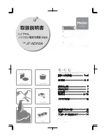
JF-ND110A
Brand: Haier Pages: 16
JF-NC429A
Brand: Haier Pages: 8
HSHF-20C
Brand: Haier Pages: 8
LW-194B
Brand: Haier Pages: 16

PFV1375MW
Brand: Premium Pages: 9

Cycle 320l
Brand: mabe Pages: 2

46501
Brand: Omcan Pages: 20

LC21
Brand: Freggia Pages: 20

HGS14355FW
Brand: Hanseatic Pages: 50

TSD-27CF
Brand: Turbo Air Pages: 26

EMR1092DS2
Brand: EAS Electric Pages: 56
GLFH1779GW - 16.7 cu. Ft. Upright Freezer
Brand: Frigidaire Pages: 13

4356739
Brand: KitchenAid Pages: 24

EUF2948IOX
Brand: Electrolux Pages: 20

EUFG29800W
Brand: Electrolux Pages: 28


