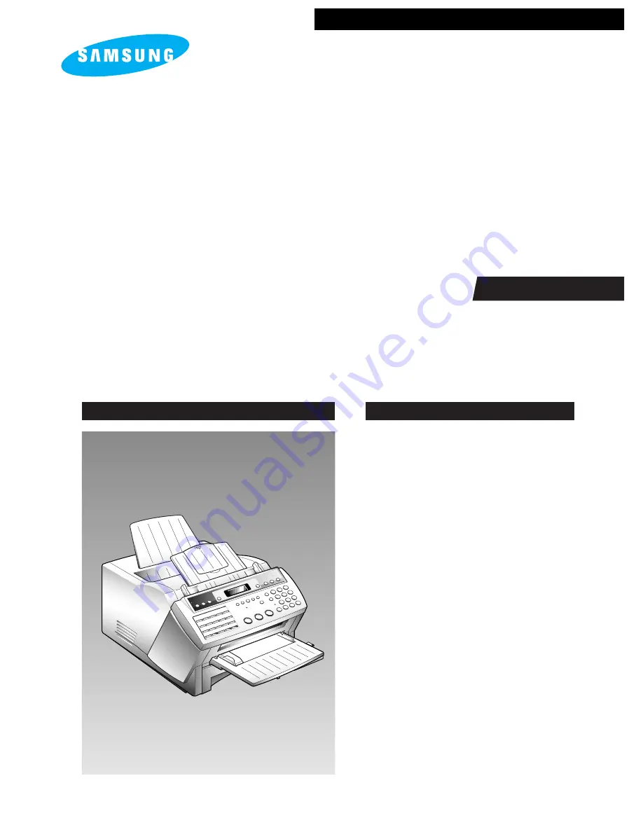
background image

FACSIMILE

SF6500/SF6600

CONTENTS

1. Precautions 

2. Specification

3. Installation

4. Theory of Operation

5. Circuit Description

6. Disassembly and Reassembly 

7. Maintenance & Troubleshooting  

8. Electrical Parts List 

9. PCB Diagrams  

10. Block Diagram

11. Wiring Diagram 

12. Schematic Diagrams

FACSIMILE

SERVICE 

Manual 

Summary of Contents for SF6500

Page 1: ...pecification 3 Installation 4 Theory of Operation 5 Circuit Description 6 Disassembly and Reassembly 7 Maintenance Troubleshooting 8 Electrical Parts List 9 PCB Diagrams 10 Block Diagram 11 Wiring Diagram 12 Schematic Diagrams FACSIMILE SERVICE Manual ...

Page 2: ...Samsung Electronics Co Ltd June 1998 Printed in Korea JC68 61013A ELECTRONICS ...

Page 3: ...es AC and high voltage power supplies Always inspect for pinched out of place or frayed wiring Do not change the spacing between components and the printed circuit board 7 Product Safety Notice Some electrical and mechanical parts have special safety related characteristics which might not be obvious from visual inspection These safety features and the protection they provide could be lost if a re...

Page 4: ...val devices not classified as anti static can generate electrical charges sufficient to damage ESDs 5 Do not use Freon propelled chemicals When sprayed these can generate electrical charges sufficient to damage ESDs 6 Do not remove a replacement ESD from its protective packaging until immediately before installing it Most replacement ESDs are packaged with all leads shorted together by conductive ...

Page 5: ... levels Printing speed 6 PPM Letter size Automatic document feeder 30 pages Phone Built in handset One touch dial 20 locations LCD 16 characters X 2 lines Dimension H X W X D 9 8 X 14 3 X 17 5 inches 249 X 363 X 446 mm trays and optional second cassette excluded Weight Approx 33 1 lb 15 kg fully equipped Approx 22 lb 10 kg cartridge and recording paper excluded Power 220V AC 50 60 Hz 2 2 Technical...

Page 6: ...lass Letter size A4 size Scanning position Top edge 2 mm 2 mm 0 079 0 079 inch Bottom edge 0 mm 2 5 mm 0 0 098 inch PRINTER Recording method Electrostatic image recording with LSU array Printing speed 6 pages Letter size minute recording density Horizontal 11 8 lines mm 300 dpi Vertical 11 8 lines mm 300 lpi Recording paper size A4 8 3 11 7 inches 210 297 mm Letter 8 5 11 inches 216 279 mm Legal 8...

Page 7: ...Ibs Printing density and uniformity Density Greater than 1 0 O D Optical Density Uniformity Less than 0 3 O D MODEM Modulation Group 3 ECM CCITT V 34 CCITT V 17 CCITT V 29 V 27ter Binary signal CCITT V 21 T 30 Tonal signal CCITT T 30 SOUND Key click Frequency 1 6 kHz Duration 30 msec Alarm Frequency 1 6 kHz Duration 2 msec Transmission completion Normal 1 sec Error 1 sec Operator call 15 sec 1 28 ...

Page 8: ...Paper Cassette Option GENERAL Dimension HWD 4 2 x 14 1 x 16 1 inches 107 x 360 x 410 mm Weight approx 11 lb 5 kg RECORDING PAPER SIZE Size Letter size 8 5 x 11 inches 216 x 279 mm A4 size 8 3 x 11 7 inches 210 x 297 mm Legal size 8 5 x 14 inches 216 x 356 mm Weight 16 24 lbs 60 90 g m2 Thickness 0 08 0 12 mm CASSETTE Basic 250 sheets Letter Legal A4 size Reference weight 75 g m2 REPLACEMENT CYCLE ...

Page 9: ...t the guides to match the width of the paper Document exit tray A4 B5 A5 A6 Ltr 3 1 Samsung Electronics 3 Installation 3 1 Document Tray 1 Insert two tabs on the document tray into the corresponding slot as shown 2 Fold out the extender on the document tray if necessary Document tray Extender Figure 3 5 Figure 3 3 Figure 3 4 Figure 3 1 Figure 3 2 3 2 Document Exit Tray and Manual Feeder for upgrad...

Page 10: ...ther end into a standard phone wall jack LINE 3 5 AC Power Cord Plug one end of the cord into the back of the machine and the other end into a standard grounded 3 prong AC power outlet The machine turns on All lamps on the control panel light up and the LCD window displays WARM UP PLEASE WAIT then NO PAPER or NO CASSETTE Load the paper as described on page 3 10 If you want to power the machine off...

Page 11: ... 2 Unplug the power cord and remove all trays from the fax machine 4 Carefully place the fax machine on top of the second cassette unit keeping the machine level Make sure the connector is properly inserted 3 Press the cover release button to open the cover and remove the toner cartridge Then close the cover 5 Press the cover release button to open the cover and install the toner cartridge Install...

Page 12: ...connector of the MFP board into its place then push down the MFP board so that the P1 connector on the MFP board is properly installed into the P3 connector on the main board Make sure the PCB supporter is also properly inserted Installation 3 4 Samsung Electronics Figure 3 14 Figure 3 15 Figure 3 16 Figure 3 17 3 7 MFP Board Option This board is required to upgrade this machine to use with PC for...

Page 13: ...his machine now you need to install this printer software 3 7 1 With Windows 3 1 1 Start Windows 2 Insert the setup diskette into drive A or B 3 In Windows Program Manager click on File then choose Run 4 In the command box type a setup or b setup then click OK 5 Follow the instructions on the installation screens 6 Restart Windows Note For the latest information on installing and using the printer...

Page 14: ...Make sure the SF6000 Series MFP is listed as your default printer in the Windows Control Panel Print as you normally would for example by choosing Print from your applications File menu CHANGING PRINTER SETTINGS 1 You can use paper sizes that are letter 8 5 X 11 inches legal 8 5 X 14 inches and A4 8 2 X 11 7 inches When you load the paper adjust the paper cassette for the paper size you chosen and...

Page 15: ...ports are configured automatically during installation The cable is also configured automatically to attach to your computer s LPT1 during installation However you can change the Cable Print or Fax configuration by pressing the Configure button Cable Port This is the computer port to which you connect the SF6000 Series MFP cable It is configured automatically to LPT1 during installation LPT1 is al...

Page 16: ...ou would normally press to close the MFP manager display and keep the MFP manager running in the background The MFP manager must be running in the background when you want to use your SF6000 Series MFP OK button This is the button you would press to terminate the MFP manager You do not want to terminate the MFP manager under normal circumstances This button is provided for the case when Windows re...

Page 17: ...You must use KM48C2100 DRAM 1 Unplug the power cord 2 Remove the two screws and pull out the board cover 3 Unplug all the connectors from the boards and take out the board cover 4 If an optional MFP board have been installed remove the MFP board See MFP Board on page 6 34 5 Insert one or two KM48C2100 DRAM IC s into the appropriate socket s on the main board Note You must observe the correct direc...

Page 18: ...nd jams Figure 3 26 6 Plug all the connectors into their places install the MFP board if required reinstall the board cover and fasten the screws 7 Plug the power cord to power the machine on 8 Get into the Tech mode by Pressing MENU 1 9 3 4 9 In Tech mode Press MENU and one touch 04 ÔSYSTEM SETUP Õ 10 Press or repeatedly until you find DRAM TEST 11 Press ENTER The LCD briefly displays TESTING the...

Page 19: ... X 279 mm A4 8 3 X 11 7 inches 210 X 297 mm To use Letter size paper change the position of the paper guide before loading paper 1 Remove one screw fastened the paper guide and take out the guide while pushing the low end inward 2 Insert the guide into the slots as shown in the figure and fasten the screw Note If you want to change the recording paper size you must set your machine to use the sele...

Page 20: ...ch are marked with the corresponding paper size 2 To move the rear guide push down the tabs of the guide and pull the guide inwards or outwards so that the tabs are placed at the desired position USING THE SIDE GUIDE 1 There are two adjustable positions for the side guide If you are using A4 size paper place the guide at the front position Otherwise place the guide at the back 2 To move the side g...

Page 21: ...e you must replace the cleaning felt If not the print quality may be degraded When you move the fax machine do not move it with the toner cartridge installed in the machine First remove the toner cartridge then carry the machine TONER CARTRIDGE 1 Press the cover release button and fully open the operation unit assembly 2 Hold the toner cartridge by the green tab and remove the used unit if necessa...

Page 22: ...ridge unit in hand fit the tabs on either side of the cartridge the either side of the compartment as shown and slide it down firmly into your fax machine until it clicks in place Warning Your machine is designed to stop the machine operation and cut off the laser beam that can damage your eye if the cover is opened However for safety s sake do not look at the LSU window in front where the laser b...

Page 23: ...how CLEANING FELT 1 Open the fuser cover by pulling the release lever 2 Remove the cleaning felt used 4 Close the fuser cover Note You must install a new cleaning felt when you install a new toner cartridge If not the print quality may be degraded Figure 3 45 Figure 3 46 Figure 3 47 Figure 3 48 ...

Page 24: ...de is used for clearing all the user s data in memory and setting to default status 1 If not in the tech mode Press MENU 1 9 3 4 in sequence to initiate the tech mode 2 Press MENU and the one touch key 5 MEMORY CLEAR The LCD displays MEMORY ALL CLEAR 3 Press 1 to clear all memory If you want to cancel press 2 The machine returns to Standby Mode 3 12 1 System Data Settings in User mode The fax mach...

Page 25: ... 1 to turn this feature on If you want to set the time duration that the machine activates the power save mode enter the time in 24 hour format Press 2 to turn this feature off Dial Mode Select the type of dial system your fax machine is connected to Press 1 if the fax machine is connected to a tone Touch Tone dial line Press 2 if the fax machine is connected to a pulse Rotary dial line Security C...

Page 26: ...mber of attempts from 0 to 7 to redial the number before giving up If you enter 0 the machine will not redial Ring Before Answer You can select the number of times your machine rings before answering an incoming call If you are using your machine as both a telephone and a fax machine we suggest you set the ring count to at least 4 to give you time to answer Enter a number from 1 through 7 on the n...

Page 27: ...ITY button again PP on the LCD disappears You can set your machine to turn the feature off automatically if there is no further data printed within 30 minutes or 8 hours after PC printing Press 1 to select 8 hours The machine turns off automatically 8 hours after PC printing is completed Press 2 to select 30 minutes The machine turns off automatically 30 minutes after PC printing is completed 3 14...

Page 28: ...set to 14400 the Rx speed can be either V 33 or V 17 speed When the Tx speed is set to 9600 or 7200 the Rx speed can be either V 29 or V 27ter speed When the Tx speed is set to 4800 or 2400 the Rx speed can be any V 27ter speed Error Rate 6 12 If the error rate exceeds the chosen rate fall back occurs which will lower the baud rate automatically down to as low as 2400 baud until the error rate is ...

Page 29: ...de the display shows one of the following PAPER JAM COMM ERROR LINE ERROR In service mode the display shows all error messages available in user mode as plus additional error messages available only in Service Mode Error messages shown in service mode only are as follows PRE MESSAGE ERROR problem occurred during phase B of session POST MESSAGE ERROR problem occurred during phase D of session MESSA...

Page 30: ...documents are stored in memory You can check it by printing the Delayed Dial List Press MENU one touch 17 DELAYED DIAL ENTER sequentially 2 Remove the paper cassette trays and toner cartridge 3 Unplug the power cord 4 Use a flat and clean surface 5 Replace with only an authorized component 6 Do not force to open or fasten a plastic material component 7 Be careful no obstacles are included when you...

Page 31: ...in the direction of B Notes When you reassemble the pad be sure that the rubber pad and holder fit into the guide boss and the holder tabs fit into the corresponding hole Then push them firmly until it clicks Clean the surface of the rubber pad with ethyl alcohol After wiping it be sure to dry completely with a soft cloth Check the rubber wear If the wear reaches 1 2 its original thickness replace...

Page 32: ... Place the unit on soft cloth to avoid the accidental scratch on the surface of the unit 3 Unplug the OPE connector from the scan PBA and remove the one earth screw 4 Open the OPE cover Twist the tie stopper until it is released The OPE unit has secured by the tabs on the bottom end to the Scan unit as shown Pull the tabs outwards so that the OPE unit is separated from the Scan unit Tab Tie stoppe...

Page 33: ... screw securing the CIS Figure 6 9 A B 4 Unplug one connector from the CIS Pull up the left end of the CIS then take out the CIS in the direction of B Figure 6 10 Notes After you replace the CIS you must perform the Make shading procedure For details see page 7 3 Check the glass surface of the CIS for any stain or scratch If stained wipe off with ethyl alcohol If it is heavily stained or scratched...

Page 34: ...h a soft cloth 6 7 Rollers ADF Feed D Exit 1 Before you disassemble the roller you should remove Scan unit See page 6 1 White roller See page 6 2 OPE unit See page 6 3 2 Remove the two screws securing the scan paper guide and take out the Scan paper guide Figure 6 8 3 Take out the rollers from the Scan unit Figure 6 12 ADF roller Feed roller D Exit roller ...

Page 35: ...e page 6 1 White roller See page 6 2 OPE unit See page 6 3 2 Turn the scan unit over and unplug the motor connector from the Scan PBA Figure 6 13 Figure 6 8 Scan Paper Guide 4 Remove the two screws securing motor cover and take out the motor cover 6 Remove the two screws securing the motor to the motor bracket Motor bracket Figure 6 14 Figure 6 16 5 Remove the two screws securing the motor to the ...

Page 36: ... scan upper frame of the OPE unit over 4 Remove the three screws and take out the spring pinch The roll pinch is separated Figure 6 17 Figure 6 18 Roll pinch Spring pinch 6 10 Scan PBA 1 Before you disassemble the Scan PBA you should remove Scan unit See page 6 1 2 Turn the Scan unit over and unplug all connectors from the scan PBA 3 Remove the one screw securing the Scan PBA and take out the PBA ...

Page 37: ... PBA side up and remove the rubber contact carefully if it is still attached into the PBA Be careful Keys and rubber contacts may be separated and you might loss any of them When you assemble the OPE unit make sure the keys are in correct position so as not to make improper contacts When you reassemble the PBA secure the screws according in the order of the number printed in the PBA After reassemb...

Page 38: ...pressing the release button on the left side of the machine Disassembly and Reassembly 6 9 Samsung Electronics Figure 6 24 Figure 6 25 2 Remove the Toner lever inserted into the main frame by squeezing both sides of the lever and pulling it out Toner Lever ...

Page 39: ...de Covers Left Right 1 Open the Control panel by hand 3 Close the Control panel and take out the Scan unit Then unplug the connector from the Scan board 4 Remove the two screws from the colored bar Then remove the four screws from each Side cover Figure 6 29 Figure 6 26 Figure 6 27 Figure 6 28 OPE Unit TX piece ...

Page 40: ...to the main frame Then take out each side cover 6 14 Top Cover 1 Before you disassemble the Top cover you should remove Side covers See page 6 10 2 Remove the four screws from the Top cover and take out the cover Note When you reassemble the Side covers you should first hook the L shaped tabs into their places and push the top side of the cover firmly Figure 6 30 Figure 6 32 Figure 6 31 ...

Page 41: ...rame and take out the Rear cover 6 16 Speaker 1 Before you disassemble the Speaker you should remove Left side cover See page 6 10 2 Remove the two screws securing the Speaker to the main frame and unplug the speaker connector Then take out the Speaker Note When you reassemble the Rear cover hook the tabs located on the lower end in place and then push the top side so that the tabs on the upper en...

Page 42: ...s spring Note When you reassemble the Latch clutch you should set the spring into the clutch as shown below then replace the clutch B A Figure 6 37 Figure 6 38 Spring Latch Clutch 6 17 Solenoid 1 Before you disassemble the Speaker you should remove Left side cover See page 6 10 2 Remove the two screws securing the Solenoid to the main frame and unplug the connector from the Mech board Then take ou...

Page 43: ...ld remove Left side cover See page 6 10 Latch clutch See page 6 13 Gear Z52 25 See page 6 14 Solenoid See page 6 13 2 Remove the E ring and take out the clutch Figure 6 39 Figure 6 40 Feed Clutch E ring Pickup Clutch E ring 6 21 Gear Z52 25 Gear Z27 1 Before you disassemble the Gear you should remove Left side cover See page 6 10 2 Remove the E ring from the Gear Z52 25 Then take out the Gear Z52 ...

Page 44: ... Board 1 Before you disassemble the Mech board you should remove Left side cover See page 6 10 2 Unplug the connector and remove the two screws from the Mech board Then take out the board 6 23 Driver 1 Before you disassemble the Driver you should remove Left side cover See page 6 10 Gear Z52 25 See page 6 14 2 Remove the six screws securing the Driver to the main frame and unplug the connector fro...

Page 45: ...m the HVPS board 6 25 Paper Empty Sensor 1 Before you disassemble the sensor you should remove Right side cover See page 6 10 2 Unplug the connector H8 from the HVPS board and release the connector wire by removing the cover switch that ties the wires in a bundle 3 Take out the board Be careful when you unplug the scan connector H13 from the Mother board Figure 6 46 Figure 6 48 Figure 6 47 HVPS bo...

Page 46: ... end of the sensor in place and push until you hear a click then push the other end 4 Take out the Sheet sensor Put a flat blade screw driver or something under the sensor through the hole on the right side of the machine and push it up 3 Press the release switch located on the right side Figure 6 49 Figure 6 51 Figure 6 52 Figure 6 50 Paper Empty Sensor Sheet cover ...

Page 47: ...ews securing the SMPS to the main frame 4 Take out the SMPS and unplug the two connectors from the SMPS board You should unplug the connector CON1 while you push the lever of the connector Note When you reassemble the SMPS make sure that the bottom of the SMPS is fitted into the groove on the main frame and lower the SMPS along the groove until the pin connector on the SMPS board clicks into the c...

Page 48: ...t push it out 3 Pull out the board in the arrow direction so that the connector CN8 is unplugged from the connector on the HVPS board Then take out the Mother board Figure 6 57 Figure 6 59 Figure 6 60 Figure 6 58 CON 1 Power Inlet Mother Board 6 27 Power Inlet 1 Before you disassemble the Power inlet you should remove Side covers See page 6 10 Top cover See page 6 11 Rear cover See page 6 12 2 Rem...

Page 49: ...ssemble the Fuser you should remove Side covers See page 6 10 Top cover See page 6 11 2 Unplug the three connectors H4 H5 H7 from the HVPS board Release the connector wires by removing the cover switch that ties the wires in a bundle Figure 6 61 Figure 6 62 Note When you reassemble the Fuser if it is difficult to plug the connector to the SMPS board take out the SMPS by removing the two screws sec...

Page 50: ...e Fuser guide Note When you reassemble Be careful not to be damaged by static electricity when you replace the LSU Static electricity affects the image quality Make sure that you do not remove the two screws located on the top of the LSU If it is difficult to plug the connectors to the Mother board remove the SMPS first and then plug in the connectors 3 Unplug the two connectors from the Mother bo...

Page 51: ... Board Notes When you replace the Main board if you find IP board next to the Main board remove the one screw securing the IP board and take out the IP board You do not have to install this IP board because new Main board contains the IP board features After you replace the Main board you must perform the Make shading test For details see page 7 3 When you reassemble the boards make sure they are ...

Page 52: ...e to the upper plate 3 Unplug the connector H9 from the HVPS board Release the connector wire by removing the cover switch that ties wires in a bundle 4 Press the release switch located on the right side 5 Remove the E ring and hinge bracket Then push the hinge shaft inwards and take it out 6 Take out the upper plate Figure 6 70 Figure 6 71 HVPS Board Figure 6 73 Figure 6 72 H9 Hinge Bracket Hinge...

Page 53: ...ee page 6 10 Top cover See page 6 11 Upper frame See page 6 23 2 Remove the four screws from the upper frame and separate the Upper frame into the Upper guide and Plate 3 Use a flat blade screw driver or something to push up the Pick up sensor from the bottom Then take out the sensor Figure 6 74 Figure 6 75 Upper Plate Pick up Sensor Upper Guide ...

Page 54: ...the four screws from the upper frame and separate the Upper frame into the Upper guide and Plate 4 Use a flat blade screw driver or something to push down the roller through the hole as shown It releases the tab latched into the Upper guide 5 Take out the Idle roller Figure 6 76 Figure 6 77 Figure 6 78 Figure 6 79 3 Remove the spring securing the Idle roller to the Upper guide Upper Plate Upper Gu...

Page 55: ...er frame See page 6 23 2 Remove the four screws from the upper frame and separate the Upper frame into the Upper guide and Plate Note Be careful to keep the surface of the roller clean Figure 6 81 Figure 6 80 3 Remove the locker secured to the roller You should pull the levers of the locker outwards to release the locker from the roller Then take out the Idle roller Transfer Roller Locker ...

Page 56: ...ngs on the both ends of the roller 2 Remove the bushings on the both ends of the roller Figure 6 82 6 37 Developer Driver 1 Before you disassemble the Developer driver you should remove Side covers See page 6 10 Top cover See page 6 11 Gear Z52 25 See page 6 14 2 Remove the two screws located next to the Gear Z52 25 Then take out the Developer driver Figure 6 83 Bushing 2 Remove the two screws loc...

Page 57: ... cover switch that ties the wire in a bundle Disassembly and Reassembly 6 28 Samsung Electronics 6 38 Guide Paper 1 Press the release switch located on the right side 2 Remove the two screws securing the Guide paper to the main frame Take it out Figure 6 85 Figure 6 86 Figure 6 87 3 Insert a flat blade screw driver or something into the hole as shown Push down to release the sensor and take it out...

Page 58: ...to release the switch 6 40 Micro Switch 1 Before you disassemble the Micro switch you should remove Side covers See page 6 10 Top cover See page 6 11 2 Unplug the connector H3 from the HVPS board then release the connector wire by removing the cover switch that ties the wire in a bundle Figure 6 88 Figure 6 89 Bracket Micro Switch Cover switch ...

Page 59: ...he Feed roller you should remove Side covers See page 6 10 Latch clutch See page 6 13 Feed clutch See page 6 14 2 Pull the bushing shaft slightly upwards and turn it 45 degrees counterclockwise so that a hole on the bushing shaft aligns with the hole on the main frame 3 Bushings are attached on both end of the roller Push outwards on the bushing shown inside on the left end of the roller Figure 6 ...

Page 60: ...htly upwards and turn it 45 degrees clockwise so that a hole on the bushing shaft aligns with the hole on the main frame 3 Bushings are attached on both end of the roller Push outwards on the bushing shown inside on the left end of the roller Figure 6 92 Figure 6 93 Bushing Shaft Bushing Pick up Roller Note Check the roller for friction and deformation If the rubber is heavily worn or stained repl...

Page 61: ...ush down at the point on the wire as shown by using a flat blade screw driver so something It allows the wire to be released from the plate 3 Press the release switch located on the right side of the main frame to open the upper frame 4 Holding each end of the plates take them out Figure 6 94 Figure 6 95 Figure 6 96 B A Note When you reassemble the plates you have to insert it into the correct pos...

Page 62: ...thin tool to be released from the main frame of the cassette and take out the pad Be careful not to lose the spring Note When you reassemble the pad frame Put the spring in place Make sure the two legs on the bottom of the pad are correctly hooked as shown below Press the pad down firmly until the tabs on each side of the pad frame are inserted in place Figure 6 98 Figure 6 100 Figure 6 99 Pad Fra...

Page 63: ...6 45 MFP Board Option 1 Remove the four screws 2 Unplug all the connectors from the boards 3 Pull up the MFP board so that the connector and PCB supporter are released Take out the MFP board Figure 6 101 Figure 6 103 Figure 6 102 PCB supporter Connector ...

Page 64: ...horized component 5 Do not force to open or fasten a plastic material component 6 Be careful no obstacles are included when you reassemble components 6 46 2 Side Covers Left Right 1 Remove the four screws securing each side cover Pull the side cover slightly upwards to take it away from the main frame 6 46 3 Motor 1 Before you disassemble the motor you should remove Left side cover See page 6 35 2...

Page 65: ...or bracket See page 6 35 2 Remove the E ring from the gear Z5513 Then take out the gear Z5513 3 Remove the gear Z27 located under the gear Z5513 6 46 7 Feed Clutch 1 Before you disassemble the feed clutch you should remove Left side cover See page 6 35 2 Remove the E ring from the feed clutch Then take out the feed clutch Figure 6 107 Figure 6 109 6 46 5 Solenoid 1 Before you disassemble the solen...

Page 66: ...t the spring in place as shown below then replace the clutch 6 46 8 Latch Clutch 1 Before you disassemble the latch clutch you should remove Left side cover See page 6 35 2 Remove the one screw and take out the latch clutch and its spring Figure 6 111 Figure 6 113 6 46 9 Idle Gear SCF 1 Before you disassemble the idle gear you should remove Solenoid See page 6 36 Pickup clutch See page 6 36 Feed c...

Page 67: ...Figure 6 115 Figure 6 117 6 To remove the feed roller pull the bushing on the left end of the feed roller slightly upwards and turn it in the direction of arrow so that a hole on the bushing aligns with the hole on the main frame then take it away from the roller shaft Now you can take out the feed roller Figure 6 116 6 46 11 Feed Roller and Idle Roller 1 Before you disassemble the rollers you sho...

Page 68: ...e 6 36 Dummy cassette See page 6 38 2 Pull the bushing on the left end of the pickup roller slightly upwards and turn it in the direction of arrow so that a hole on the bushing aligns with the hole on the main frame then take it away from the roller Then take out the pickup roller Figure 6 118 Figure 6 120 6 46 13 SCF Connector 1 Before you disassemble the connector you should remove Left side cov...

Page 69: ...river or a thin tool to be released from the main frame of the cassette and take out the pad Be careful not to lose the spring Note When you reassemble the pad frame Put the spring in place Make sure the two legs on the bottom of the pad are correctly hooked as shown below Press the pad down firmly until the tabs on each side of the pad frame are inserted in place Figure 6 121 Figure 6 123 Figure ...

Page 70: ... EFFFF E00000 DFFFF C00000 BFFFF 800000 7FFFF 400000 3FFFF 000000 ON CHIP INTERNAL REGISTER 1 Mbyte I O 1 Mbyte SRAM 2 Mbyte EPROM 4 Mbyte DRAM 4 Mbyte DRAM 4 Mbyte CPU A16 A23 ADO AD15 INT HOLD CAS WEO WE1 WEO WE1 DRQ DAK TRIG CS RESET PIC_ CS PIC_ INT PIC_ DRQ DDIN PIC DARK HBE ADS DDIN MCS RD WEO MIRQ CLOCK ADO AD7 MA1 MA5 MODEM ECP ADO AD15 MA1 MA7 SYSTEM CONTROLLER ADO AD15 MA1 MA11 ADO AD15 ...

Page 71: ... in Even byte when WE0 goes Low Odd byte when WE1 goes Low and Word wide when both signals go Low DRAM access is controlled by RAS0 RAS1 and CAS In order to access 8 Mbyte RAS0 is bank selected by ASIC 5 1 6 Scanner Control IMAGE SENSOR The CIS equipped with 300 dpi scanning density and 2 5 ms for 1 line storage time IMAGE PROCESSOR It supplies clock signal into CIS and performs shading correction...

Page 72: ...400 VDC bias voltage into the magnet roller 1100 VDC charging voltage into charging roller 4000 VDC transfering voltage and 900 VDC retransfering voltage into the transfer roller 5 5 Scan PBA This board consists of Scan motor drive IC SLA7024M CIS and OPE PBA interface connector It is connected to the main board through the mother board 5 6 Mech PBA This board contains the main motor driver IC SLA...

Page 73: ...r line The function diagram is provided below 5 8 1 Modem AFE and Interface TIT Transformer Input from Transformer The signal is applied to LIU input of the modem ROT Receive Output to Transformer The signal from line is applied to modem Figure 5 4 LIU Function Diagram Figure 5 5 Modem AFE and Interface AC coupliy Capacitor TIP RING HOOK off 2 EXT LINE RINGER RING DET X tal NPO Key input RCV Rx SI...

Page 74: ...8 Off Hook Detect 5 8 3 Off Hook Detect EHS Electronic Hook Switch This signal comes to ILIU chip when CML relay turns on and applies to CPU through UART Rx MHS Manual Hook Switch This signal comes to ILIU chip through hook switch when the handset is off hooked and applies to CPU through UART Rx 5 8 2 UART Rx Tx TxD Transmit Data Output This data signal is transferred to CPU through ILIU chip RxD ...

Page 75: ... Dialing 5 8 5 MF DP Dialing DP dialing is activated by receiving digital data from CPU through UART Tx The signal turns on and off Q2 through ILIU chip and DPN It causes Q1 to be on and off to generate the dial pulse MF dialing is activated by receiving digital data from CPU through UART Tx ILIU chip adjusts DTMF frequency and level through RFO and RFI and sends out the DTMF signal RFO 4 9 C14 C1...

Page 76: ...age consists of start up snubber circuit voltage control drive circuit Output stage Output smoothing circuit Voltage detector circuit This circuit detects the output voltage and feeds it back to the converter stage Lamp voltage control circuit Figure 5 11 SMPS Block Diagram AC INPUT AC120V 60Hz LINE FILTER LAMP CONTROL CIRCUIT TO LAMP LAMP CONTROL SIGNAL INPUT START UP VOLTAGE CONTROL AND DRIVE CI...

Page 77: ... paper feeding clutch controller and interface signal controller The 480 kHz resonator generates 373 pps motor phase using the binary counter to drive the motor SCF I O Control Signal Circuit Description Pin no Pin name Description Status CN1 2 SCF_SEL SCF select L SCF CN1 3 SCFMTRSTRT SCF motor start L start CN1 4 SCFCLTCH SCF clutch control H paper feed CN1 5 SCFPEMPT SCF paper empty L no paper ...

Page 78: ... EFFFF E00000 DFFFF C00000 BFFFF 800000 7FFFF 400000 3FFFF 000000 ON CHIP INTERNAL REGISTER 1 Mbyte I O 1 Mbyte SRAM 2 Mbyte EPROM 4 Mbyte DRAM 4 Mbyte DRAM 4 Mbyte CPU A16 A23 ADO AD15 INT HOLD CAS WEO WE1 WEO WE1 DRQ DAK TRIG CS RESET PIC_ CS PIC_ INT PIC_ DRQ DDIN PIC DARK HBE ADS DDIN MCS RD WEO MIRQ CLOCK ADO AD7 MA1 MA5 MODEM ECP ADO AD15 MA1 MA7 SYSTEM CONTROLLER ADO AD15 MA1 MA11 ADO AD15 ...

Page 79: ... in Even byte when WE0 goes Low Odd byte when WE1 goes Low and Word wide when both signals go Low DRAM access is controlled by RAS0 RAS1 and CAS In order to access 8 Mbyte RAS0 is bank selected by ASIC 5 1 6 Scanner Control IMAGE SENSOR The CIS equipped with 300 dpi scanning density and 2 5 ms for 1 line storage time IMAGE PROCESSOR It supplies clock signal into CIS and performs shading correction...

Page 80: ...400 VDC bias voltage into the magnet roller 1100 VDC charging voltage into charging roller 4000 VDC transfering voltage and 900 VDC retransfering voltage into the transfer roller 5 5 Scan PBA This board consists of Scan motor drive IC SLA7024M CIS and OPE PBA interface connector It is connected to the main board through the mother board 5 6 Mech PBA This board contains the main motor driver IC SLA...

Page 81: ...r line The function diagram is provided below 5 8 1 Modem AFE and Interface TIT Transformer Input from Transformer The signal is applied to LIU input of the modem ROT Receive Output to Transformer The signal from line is applied to modem Figure 5 4 LIU Function Diagram Figure 5 5 Modem AFE and Interface AC coupliy Capacitor TIP RING HOOK off 2 EXT LINE RINGER RING DET X tal NPO Key input RCV Rx SI...

Page 82: ...8 Off Hook Detect 5 8 3 Off Hook Detect EHS Electronic Hook Switch This signal comes to ILIU chip when CML relay turns on and applies to CPU through UART Rx MHS Manual Hook Switch This signal comes to ILIU chip through hook switch when the handset is off hooked and applies to CPU through UART Rx 5 8 2 UART Rx Tx TxD Transmit Data Output This data signal is transferred to CPU through ILIU chip RxD ...

Page 83: ... Dialing 5 8 5 MF DP Dialing DP dialing is activated by receiving digital data from CPU through UART Tx The signal turns on and off Q2 through ILIU chip and DPN It causes Q1 to be on and off to generate the dial pulse MF dialing is activated by receiving digital data from CPU through UART Tx ILIU chip adjusts DTMF frequency and level through RFO and RFI and sends out the DTMF signal RFO 4 9 C14 C1...

Page 84: ...age consists of start up snubber circuit voltage control drive circuit Output stage Output smoothing circuit Voltage detector circuit This circuit detects the output voltage and feeds it back to the converter stage Lamp voltage control circuit Figure 5 11 SMPS Block Diagram AC INPUT AC120V 60Hz LINE FILTER LAMP CONTROL CIRCUIT TO LAMP LAMP CONTROL SIGNAL INPUT START UP VOLTAGE CONTROL AND DRIVE CI...

Page 85: ... paper feeding clutch controller and interface signal controller The 480 kHz resonator generates 373 pps motor phase using the binary counter to drive the motor SCF I O Control Signal Circuit Description Pin no Pin name Description Status CN1 2 SCF_SEL SCF select L SCF CN1 3 SCFMTRSTRT SCF motor start L start CN1 4 SCFCLTCH SCF clutch control H paper feed CN1 5 SCFPEMPT SCF paper empty L no paper ...

Page 86: ...6 31 See p 6 30 See p 6 26 See p 6 20 See p 6 15 See p 6 33 CLEANING CYCLE 6 Months 6 Months 6 Months 6 Months Error Message Description Solution BUSY REDIAL The machine is waiting the programmed You can press START to immediately redial interval to automatically redial or STOP to cancel the redial operation COMM ERROR A problem with the facsimile Try again communications has occurred INCOMPATIBLE...

Page 87: ...SSETTE The printer system stops cassette OVERHEAT The printer part has overheated Your unit will automatically return to the standby mode when it cools down to normal operating temperature If failure persists call service PAPER JAM 0 Recording paper has jammed in paper Press STOP and clear the jam feeding area PAPER JAM 1 Recording paper has jammed inside Clear the jam the unit PAPER JAM 2 The jam...

Page 88: ...l MODEM TEST This test causes the machine to generate a particular frequency to verify the operation of the modem control circuits and the modem MEMORY TEST This test is used for checking the Random Access Memory RAM on the main PBA If all memory is working normally the LCD shows TESTING OK When this testing is carried out any picture data stored in memory is erased ROM TEST This test mode will di...

Page 89: ...ss or until REMOTE DIAGNOSIS PROTECTION is displayed 3 Press ENTER 4 Press 1 for protection or press 2 to allow remote diagnosis 5 Press ENTER 6 Press STOP to exit routine S NSF 61005020003380140200001302090018010000 S R FCF FIF DATA ASCII S CSI 2020202020202020202020202O20202020202020 S CSI 202020202020202020202022O202020220202020 R TSI 2020202020202020202020202O20202020202020 S DIS 00000000 0111...

Page 90: ...hart 7 4 10 See chart 7 4 11 See chart 7 4 12 END See chart 7 4 8 See chart 7 4 9 See chart 7 4 5 See chart 7 4 3 Plug the power cord Load document Copy OK Lift the handset Do you hear dial tone PC printing OK Sending OK Auto answer Manual operation RX OK Press COPY button CIS on Document fed LCD display is on System initialized 7 4 Troubleshooting Flow chart 7 4 1 Overall ...

Page 91: ... 5 V OK Normal A END Fuse remain good Check AC voltage 220 VAC Notify customer Connect as required 1 Unplug machine 2 Check fuse 1 Replace fuse 2 Plug in machine Check power supply voltage Measure voltage on the scan b d CN7 1 Measure on the OPE b d CN1 1 Replace harness Check harness Replace OPE b d and LCD module Check harness Replace harness Replace power supply ...

Page 92: ...nd LCD module Replace the main b d Replace the main b d Check CPU RSTO pin 67 of U18 in the main board Check system clock pin 50 of U18 in the main board Start END Logic H Replace the OPE board Check Vcc 5 V from P1 16 to P1 18 Vcc 4 5V 19 6608 MHz Replace power supply Replace the main board 7 4 3 System Not Initialized ...

Page 93: ...fed 24 V Check the OPE MICOM Check LCD display when document is loading Replace the OPE board Replace mother b d Check motor pulse P1 9 10 11 12 in the main board 5V 0V Check 24V motor enable P2 27 in the main board Replace the main b d Replace the motor ass y Replace the scan b d Check 24V from P19 20 of CN7 in the scan b d 7 4 4 Malfunction on Document Feeding ...

Page 94: ...7 4 5 CIS LED Not Lit START See chart 7 4 4 Load document in feeder Works properly Normal 5 V CIS LED lights Check 5V 12V P1 16 17 18 P1 1 in the main b d Replace the power supply Replace CIS Replace the main b d Check PIN27 of U25 END Press the COPY button Document fed ...

Page 95: ...e chart 7 4 5 1 1 Load document in feeder Replace CIS Replace the main b d Replace the scan b d Check harness Replace the power supply Replace the harness Measure LED 12V on scan b d CN 3 9 12 V Good Copy produced Press the COPY button Document fed CIS LED on Copy works properly Normal Check CIS clock P2 16 in the main board 5V 0V ...

Page 96: ...amsung Electronics Maintenance Troubleshooting Y Y Y Y N N N N 1 Run the printer test Run the CIS test Replace the CIS Replace the main b d END Good copy quality Normal Good copy quality Good printer quality ...

Page 97: ...nics 7 12 Y Y Y N N N 7 4 7 Malfunction in Auto Answer START END Call the machine from another phone Check ring signal on P4 8 in main b d Check ring signal on U1 25 28 in LIU b d Replace the LIU b d Replace the main b d Auto answer Normal 5V 0V ...

Page 98: ... Y N N N Y 7 4 8 Malfunction in Manual Receiving START END Press OHD and press START Check signal in P4 12 in main b d Replace the main b d Replace the LIU b d Replace the flat cable Check control signal P1 13 14 in the LIU b d Goes on line Logic L Logic L ...

Page 99: ... 9 Malfunction in Automatic Receiving START See chart 7 4 7 END END Call the machine from another phone Check the telephone line Check Tx Rx signal in P1 4 P1 7 in the LIU b d Replace the main b d Auto answer Normal Normal Notify to customer Replace the LIU b d Receive data ...

Page 100: ...ing Y Y Y N N N 7 4 10 Malfunction in Transmission START See chart 7 4 4 END Load document in feeder Call the receiving machine Press the START button Replace the LIU b d Replace the main b d Document fed The document sends out Sending works properly ...

Page 101: ...sion editor Run MFP825 control program Run Print test page Setup MFP825 Printer driver Check application S W Replace centronics cable Install MFP board correctly Replace MFP board Replace Main b d Check bi directional centronics cable Make sure the MFP board is installed properly Printer self test Works properly Works properly Works properly OK OK OK ...

Page 102: ...aling tapes on the toner cartridge removed N N Y Y N Remove the sealing tapes N Y N Y Y A B START Is there any image printed Does the cartridge work normally Does the trouble occur even with another cartridge Check the HVPS and replace the HVPS necessary Replace the cartridge 7 4 12 No Paper of the Image All white printed ...

Page 103: ...unit Does the trouble occur even with another toner cartridge Check the developer driver unit and then replace it if necessary See page 6 27 Replace the toner cartridge Check the LSU unit and then replace it if necessary Replace the transfer roller Replace the HVPS or connect the harness properly Nomal voltage in HVPS Its wiring harness O K ...

Page 104: ...replace it if necessary Replace the HVPS or connect the wiring harness properly Replace the HVPS or connect the wiring harness properly Replace the transfer unit See page 6 26 Replace the cartridge See page 3 14 Is the transfer unit O K 7 4 13 Pale Weak Image Quality 7 4 14 High Background Density Toner in the background areas N START Does the trouble occur even with another cartridge Check HVPS a...

Page 105: ...the cartridge Does the trouble occur even with another cartridge 7 4 16 All Black Printed N N Y Y N Y START Is the drum installed properly Is charge wring harness in HVPS O K Check the LSU unit and then replace it if necessary Connect the harness properly or replace it N Y Does the trouble occur even with anther HVPS Replace the HVPS Replace the cartridge Replace drum properly Does the trouble occ...

Page 106: ...rouble occur even with another cartridge N Y Replace the fuser unit Is the heat roller of the fuser unit damaged Pattern test O K N Y N Y Occured during copying Check the LSU unit and then replace it if necessary Replace the cartridge Check CIS or white roller and then replace it if necessary Does the trouble occur even with another cartridge N Y Replace the fuser unit Is the heat roller of the fu...

Page 107: ...he heat roller of the fuser unit damaged Replace fuser unit Replace the cartridge 7 4 18 Black Horizontal Line N N Y Y N Y START Is the heat roller of the fuser unit damaged Check the LSU unit and then replace it if necessary Replace the fuser unit Replace the fuser felt Replace the cartridge Does the trouble occur even with another fuser felt Does the trouble occur even with another cartridge ...

Page 108: ...ith another cartridge Y N Replace the HVPS or connect the harness properly Nomal voltage in HVPS Its wiring harness O K Pattern test O K N Y N Y Occured during copying Check the LSU unit and then replace it if necessary Check CIS and then replace it if necessary Does the trouble occur even with another cartridge Y N Pattern test O K Nomal voltage in HVPS Its wiring harness O K Replace the cartridg...

Page 109: ...eshooting Samsung Electronics 7 24 7 4 21 Avoid the Image Y N START Nomal voltage in HVPS Its wiring harness O K Check the transfer roller and then replace it if necessary Replace the HVPS or connect the harness properly ...

Page 110: ...mal Replace 2 nd cassette b d Replace motor ass y END Replace main b d 0V Check SCF CLUTCH on the 2 nd cassette b d CN2 6 Measure voltage on the 2 nd cassette b d CN1 1 Replace 2 nd cassette b d Check harness and replace harness Check SCF START on the 2 nd cassette b d CN1 3 Replace solenoid 24V 0V 7 4 22 Second Paper Cassette Option MALFUNCTION ON PAPER FEEDING ...

Page 111: ...0903 000193 U4 IC REAL TIME CLOCK 6355 1 0909 000106 U37 IC ANALOG SWITCH MC14051B 1001 000170 U21 45 IC ANALOG SWITCH MC14053B 1001 000171 U10 15 IC DRAM 48C2100C 2Mx8BIT 1105 001185 U46 IC MODEM R288FV34 1205 001421 U6 12 IC SRAM 62256B 32Kx8BIT S 1106 000197 U35 IC SRAM 6264 8KX8BIT SOP 1106 000273 U27 IC AUDIO AMP 34119 SOP 8P 1201 000105 U16 IC OP AMP 82 SOP 8P 150MI 1201 000178 U17 IC OP AMP...

Page 112: ... 10W DA 2007 000401 R248 R CHIP 150ohm 5 1 10W DA 2007 000401 R119 285 R CHIP 17 4Kohm 1 1 10W 2007 000435 R161 164 169 170 171 R CHIP 180ohm 5 1 10W DA 2007 000449 R249 251 R61 R CHIP 180ohm 5 1 10W DA 2007 000449 R14 77 133 144 280 R CHIP 1Kohm 5 1 10W DA 2007 000468 R253 256 R CHIP 1Kohm 5 1 10W DA 2007 000468 R168 180 181 R CHIP 1Kohm 5 1 10W DA 2007 000468 R272 273 292 293 R CHIP 1Kohm 5 1 10...

Page 113: ... R CHIP 137Kohm 1 1 10W D 2007 007159 C1 3 6 9 10 12 16 17 C CERAMIC CHIP 100nF 80 2203 000192 C24 26 29 30 38 40 C CERAMIC CHIP 100nF 80 2203 000192 C42 44 47 48 50 52 C CERAMIC CHIP 100nF 80 2203 000192 C54 55 66 68 70 72 C CERAMIC CHIP 100nF 80 2203 000192 C75 78 81 83 87 C CERAMIC CHIP 100nF 80 2203 000192 C93 96 97 C CERAMIC CHIP 100nF 80 2203 000192 C99 101 139 208 210 C CERAMIC CHIP 100nF 8...

Page 114: ...193 C53 59 C CERAMIC CHIP 15pF 5 50 2203 001517 C74 82 C AL SMD 10uF 20 35V GP 2402 000117 C85 C AL SMD 1uF 20 50V GP T 2402 000122 C202 203 204 205 C AL SMD 22uF 20 16V 5 2402 000135 C227 228 C AL SMD 22uF 20 16V 5 2402 000135 C11 C AL SMD 100uF 20 16V 2402 000168 C164 C AL SMD 33uF 20 35V 2402 000172 C77 C AL SMD 4 7uF 20 35V 2402 000173 C13 229 C AL SMD 10uF 20 16V GP 2402 000176 C25 219 C TA C...

Page 115: ...44 U1 1 U2 1 SOCKET IC 32P DIP SN 2 54 3704 000255 P4 CONNECTOR FPC FC PIC 14P 3708 000158 P3 CONNECTOR SOCKET 40P 2R 2 3710 000490 JP1 CONNECTOR HEADER NOWALL 2 3711 001422 P1 CONNECTOR HEADER NOWALL 2 3711 002003 P2 CONNECTOR HEADER BOX 32P 3711 003136 BATT1 BATTERY LI 3V 220mAH BUTT 4301 000108 BATT2 BATTERY NIH 2ND 4 8V 70m 4302 001005 PCB JG41 10093B ...

Page 116: ...R9 REF CHIP 10 5 1 8W 2007 000312 R11 REF CHIP 200 5 1 8W 2007 000542 R12 REF CHIP 10K 5 1 8W 2007 000303 R13 REF CHIP 22K 5 1 8W 2007 000589 R14 REF CHIP 680 5 1 8W 2007 001121 R15 REF CHIP 10K 5 1 8W 2007 000303 R16 R23 REF CHIP 22K 5 1 8W 2007 000589 R24 REF CHIP 200 5 1 8W 2007 000542 R25 REF CHIP 150 5 1 8W 2007 000403 R26 REF CHIP 300 5 1 8W 2007 000730 R27 REF CHIP 2 2K 5 1 8W 2007 000496 R...

Page 117: ...ODE REMARK MISCELLANEOUS J1 REF CHIP 0 5 1 8W 911 710007CR J5 J17 REF CHIP 0 5 1 8W 911 710007CR JP1 WIRE TCWA 3812 000101 JP3 JP11 WIRE TCWA 3812 000101 PCB OPE PCB JG41 10088A S1 INTERRUPTER TR 895 610013AA S2 PHOTO TR 0604 001006 Y1 CRESO 7 37M 0 5 2802 000185 ...

Page 118: ...m 5 1 8W DA 2007 001041 R38 R CHIP 750ohm 5 1 8W DA 2007 001159 C7 C8 C CERAMIC CHIP 100nF 10 2203 000208 C1 4 C CERAMIC CHIP 820pF 5 5 2203 003084 L1 L2 R3 R4 CORE FERRITE BEAD AB 3 2x 3301 000370 U1 U2 IC MOTOR DRIVER PBL3717A 1003 000243 R9 10 R CARBON 0 5ohm 5 1 2W A 2001 000202 C11 C AL 33uF 20 50V GP TP 6 2401 001197 C6 C AL 47uF 20 35V GP TP 6 2401 001553 CN3 CONNECTOR HEADER 3WALL 10 3711 ...

Page 119: ...DER 20P 2 2R S 3711 002001 CN4 CON 3WALL HEADER 15P 3711 000428 CN5 C0N BOX HEADER 6P 3711 000051 CN6 C0N BOX HEADER 5P 3711 003151 CN7 CON 1WALL 20P 1R 2mm S 3711 001857 CN8 CON NOWALL 70203 0048 TRANSISTORS Q1 TR SMALL SIGNAL 0501 000317 Q2 TR SMALL SIGNAL 0501 000398 PCB PCB MOTHER PCB JG41 10089A RESISTORS R1 R METAL 10K 1 8W 2004 000222 R2 REF CR 1 2K 5 1 4W 2001 000044 R3 R METAL 2 2K 1 8W 2...

Page 120: ...REC SOD 123 0401 000116 D2 DIODE REC SOD 123 0401 000116 D3 DIODE REC EK 04 DO 4 0402 000208 D4 DIODE REC EK 04 DO 4 0402 000208 PCB PCB MECH PCB JG41 10091A RESISTORS R1 REF CHIP 47K 5 1 8W 2007 000944 R2 REF CHIP 47K 5 1 8W 2007 000944 R3 REF CHIP 4 7K 5 1 8W 2007 000875 R4 REF CHIP 4 7K 5 1 8W 2007 000875 R5 REF CHIP 2 4K 5 1 8W 2007 000513 R8 REF CHIP 2 4K 5 1 8W 2007 000513 R9 REF CHIP 620 5 ...

Page 121: ...634 C14 CERAMIC 22P 5 1H 2203 000634 C15 CERAMIC 22P 5 1H 2203 000634 C16 CERAMIC 22P 5 1H 2203 000634 C17 CHIP 100N 20 1H 2203 000192 C18 CHIP 100N 20 1H 2203 000192 C19 CHIP 100N 20 1H 2203 000192 C20 CERAMIC 22P 5 1H 2203 000634 C20 CERAMIC 22P 5 1H 2203 000634 C21 CERAMIC 22P 5 1H 2203 000634 C22 CERAMIC 22P 5 1H 2203 000634 C23 CERAMIC 22P 5 1H 2203 000634 C24 CERAMIC 22P 5 1H 2203 000634 C25...

Page 122: ...2203 000408 C47 C CHIP 180P 5 1 10W 2203 000408 C48 C CHIP 180P 5 1 10W 2203 000408 C49 C CHIP 180P 5 1 10W 2203 000408 C50 C CHIP 180P 5 1 10W 2203 000408 C51 C CHIP 180P 5 1 10W 2203 000408 C52 C CHIP 180P 5 1 10W 2203 000408 C53 C CHIP 180P 5 1 10W 2203 000408 C54 C CHIP 180P 5 1 10W 2203 000408 C55 C CHIP 100N 20 1H 2203 000192 C56 C CHIP 180P 5 1 10W 2203 000408 PCB PCB ECP PCB JG41 10094A RE...

Page 123: ...P 1K 5 1 10W 2007 000468 R25 REF CHIP 1K 5 1 10W 2007 000468 R26 REF CHIP 1K 5 1 10W 2007 000468 R27 REF CHIP 1K 5 1 10W 2007 000468 R28 REF CHIP 1K 5 1 10W 2007 000468 R29 REF CHIP 1K 5 1 10W 2007 000468 R30 REF CHIP 1K 5 1 10W 2007 000468 R31 REF CHIP 1K 5 1 10W 2007 000468 R32 REF CHIP 4 7K 5 1 10W 2007 000872 R33 REF CHIP 10K 5 1 10W 2007 000300 R34 REF CHIP 10K 5 1 10W 2007 000300 R35 REF CHI...

Page 124: ...2 R60 CHIP 47 5 1 10W 2007 000947 R61 CHIP 47 5 1 10W 2007 000947 R62 CHIP 47 5 1 10W 2007 000947 R63 REF CHIP 4 7K 5 1 10W 2007 000872 R64 REF CHIP 4 7K 5 1 10W 2007 000872 R65 REF CHIP 4 7K 5 1 10W 2007 000872 R66 REF CHIP 4 7K 5 1 10W 2007 000872 R67 REF CHIP 4 7K 5 1 10W 2007 000872 R68 REF CHIP 4 7K 5 1 10W 2007 000872 R69 REF CHIP 4 7K 5 1 10W 2007 000872 R70 REF CHIP 4 7K 5 1 10W 2007 00087...

Page 125: ...1021 P_EMPTY PHOTO INTERRUPTER 0604 001020 P_EXIT PHOTO INTERRUPTER 0604 001015 PICK_UP PHOTO INTERRUPTER 0604 001022 SMPS POWER UNIT JG44 10054A SPEAKER AUDIO SPEAKER 3001 000214 TX_MOTOR TX STEPING MOTOR 3101 001007 RX_MOTOR RX STEPING MOTOR 3101 001004 LSU LASER SCAN UNIT JG59 10001A SOLENOID UNIT SOLENOID JG59 10002A NO DESCRIPTION CODE REMARK MISCELLANEOUS P1 CON WALL HEADER 7P 2 STRA 3711 00...

Page 126: ...IRE HARNESS SCAN CIS JG39 40145A CBF CBF WIRE MOTOR DRIVE GND MOTOR DRIVE GND JG39 40166A CBF CBF WIRE MOT GND MOD GND JG39 40142A CBF CBF WIRE FEED GND FEED GND JG39 40153A CBF HVPS WIRE CC WIRE JG39 40143A CBF HVPS WIRE TC WIRE JG39 40143A CBF HVPS WIRE BIAS WIRE JG39 40143A CBF EARTH WIRE OPC ERTH WIRE JG39 40141A CBF EARTH WIRE FUSER EARTH WIRE JG39 40155A CBF 2PIN WIRE HARNESS COVER S W JG39 ...

Page 127: ...25 30 105 C KMG400V100uF SAMYOUNG SAMHWA C8 M F 400V 104K MMW400V104K DONGSUNG TM2G104K SAMHWA C10 M F 400V 104K MMW400V104K DONGSUNG TM2G104K SAMHWA C11 CERAMIC 1KV 471 CKR3A471K06BS SAMHWA HCYE3A471KB SEMCO C12 MYLAR 100V 223J TY2A223J SAMHWA 50V 223J TS1H223J SAMHWA C13 MYLAR 100V 223J TY2A223J SAMHWA 50V 223J TS1H223J SAMHWA C14 MYLAR 100V 223J TY2A223J SAMHWA 50V 223J TS1H223J SAMHWA C15 CERA...

Page 128: ...SAMYOUNG SG50V100uF SAMHWA C31 CERAMIC 50V 104Z CCYV1H104ZB SEMCO CGF1H104ZFK SAMHWA C32 CERAMIC 50V 104Z CCYV1H104ZB SEMCO CGF1H104ZFK SAMHWA C33 CERAMIC 50V 104Z CCYV1H104ZB SEMCO CGF1H104ZFK SAMHWA C34 CERAMIC 1KV 101 CKR3A101K06BS SAMHWA HCYE3A101KB SEMCO RESISTORS R1 CARBON 1 2W 560K J ABCO PILKOR R2 METAL OXIDE 1W 220K J MINI PILKOR ABCO R3 METAL OXIDE 1W 220K J MINI PILKOR ABCO R4 METAL OXI...

Page 129: ... R20 CARBON 1 8W 22K J PILKOR ABCO R24 CARBON 1 8W 100 J ABCO PILKOR R25 CARBON 1 8W 100 J ABCO PILKOR R26 CARBON 1 4W 3 9K J ABCO PILKOR R27 METAL OXIDE 1W 1 2K J MINI PILKOR ABCO R28 CARBON 1 8W 2 4K J ABCO PILKOR IC s IC2 REGULATOR 12V 0 5A KA78M12 SEC IC3 REGULATOR 12V 0 5A KA79M12 SEC IC4 SHUNT REG 40V 0 1A KA431AZ SEC IC5 REGULATOR 5V 1 5A SI 3051N SANKEN DIODES BD1 BRIDGE 600V 3 0A D3SB60 S...

Page 130: ...M KOREA UZ6 2BM UNIZON ZD3 ZENER 0 5W 27V MTZ27C ROHM KOREA UZ27BM UNIZON Q1 FET POWER 800V 4A SSP4N80 SEC 2SK2669 SANKEN Q2 SWITCHING 80V 0 7A KSC1008 Y SEC Q3 SWITCHING 80V 0 7A KSC1008 Y SEC Q4 SWITCHING 500V 3A KSC5020 O SEC TRA1 TRIAC 600V 12A BTA12 600BM SGS PC1 PHOTO COUPLER 5KVac 50mA PC123FY SHARP PC2 PHOTO COUPLER 5KVac 50mA PC123FY SHARP PC3 PHOTO TRIAC 5KVac 50mA MOC3061 MOTOROLA S21MD...

Page 131: ...INE FILTER 2mH 32 21 0 8 22T LFPS 80022 JBM SUNGWON LF2 LINE FILTER UU1116 0 4 40T US40040 SUNGWON JBM L1 CHOCK COIL 0 8 68T 210uH TO 80 1603 SUNGWON B1 BEAD 3 5 5 BFS3550AO R2F SAMHWA B2 BEAD 3 5 5 BFS3550AO R2F SAMHWA RL1 RELAY 24VDC 5A KM11 M24F CHUNGWON F1 FUSE GLASS 50T050H 250V 5A TRIAD F2 FUSE GLASS 50T016H 250V 1 6A TRIAD LFT2 TRANS POWER EER 28L SUNGWON ...

Reviews: