background image

DVD-VCR COMBINATION

Chassis : Zeus EUROPE
DVD-V5450/XEF, XEB, XEU, XEN, XEC,

XEE, XEG, COM, EUR, XEH,
XEO

DVD-V5350/XET
DVD-V5500/XEH
DVD-V6400/XEF, XEB, XEU, XEN, XEC,

XEE, XEG, COM, EUR, XEH,
XEO, 

DVD-V6450/XET
DVD-V6500/XEH 

SERVICE 

Œ

Œ  

82mm Slim, Design

´

´  

MP3,VCD Playdack

ˇ

ˇ  

Divx Playack Support (Model Option)

¨

¨  

Progressive Video out

ˆ

ˆ  

6Head Hi-Fi VCR

Ø

Ø  

WHA Playback Support

Manual 

DVD-VCR COMBINATION

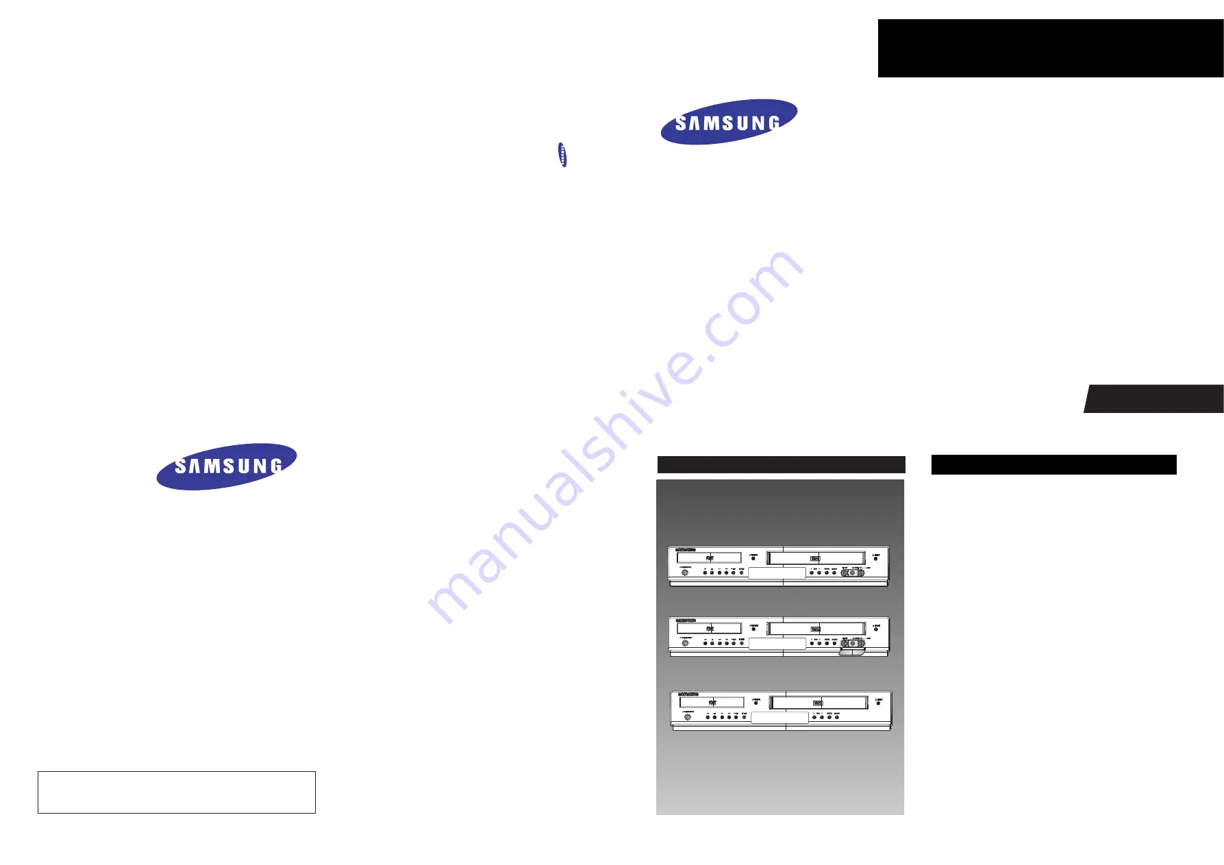
Merit & Character regarding Product

SERVICE MANUAL

DVD-V5450/V5350/V5500/V6400/V6450/V6500

DVD-V5500

DVD-V6500

DVD-V5450/V5350/V6400/V6450

ELECTRONICS

© Samsung Electronics Co., Ltd. 

JUN. 2005

Printed in Korea

AK82-00934A

This Service Manual is a property of Samsung Electronics Co.,Ltd.

Any unauthorized use of Manual can be punished under applicable 

international and/or domestic law.

Summary of Contents for DVD-V5450

Page 1: ...el Option Progressive Video out ˆ ˆ 6Head Hi Fi VCR Ø Ø WHA Playback Support Manual DVD VCR COMBINATION Merit Character regarding Product SERVICE MANUAL DVD V5450 V5350 V5500 V6400 V6450 V6500 DVD V5500 DVD V6500 DVD V5450 V5350 V6400 V6450 ELECTRONICS Samsung Electronics Co Ltd JUN 2005 Printed in Korea AK82 00934A This Service Manual is a property of Samsung Electronics Co Ltd Any unauthorized u...

Page 2: ...t Specification 2 2 2 3 Option Product Specification 2 3 2 4 Introduction to DVD 2 4 2 5 DVD Video Fromat 2 6 3 Alignment and Adjustments 3 1 3 16 3 1 VCR Adjustment 3 1 3 2 DVD Adjustment 3 6 3 3 VCR Mechanical Adjustment 3 9 4 Disassembly and Reassembly 4 1 4 26 4 1 Cabinet and PCB 4 1 4 2 Circuit Board Locations 4 3 4 3 VCR Deck Parts Locations 4 4 4 4 VCR Deck 4 7 4 5 The table of cleaning Lub...

Page 3: ...4 DVD Mechanical Parts 6 8 7 Electrical Parts List 7 1 7 14 8 Block Diagram 8 1 8 2 9 Wiring Diagram 9 1 9 2 10 PCB Diagrams 10 1 10 6 10 1 VCR Main PCB 10 2 10 2 DVD Main PCB 10 4 10 3 Front PCB 10 6 11 Schematic Diagrams 11 1 11 16 11 1 S M P S 11 2 11 2 Power Drive 11 3 11 3 Syscon Servo 11 4 11 4 Logic 11 5 11 5 A V 11 6 11 6 Hi Fi 11 7 11 7 A2 NICAM 11 8 11 8 SECAM Option 11 9 ...

Page 4: ...ation 12 1 12 60 13 Circuit Operating Descriptions 13 1 13 52 13 1 Power Supply Free Voltage 13 1 13 2 System Control 13 6 13 3 Servo 13 16 13 4 VCR Video 13 21 13 5 Hi Fi Audio 13 28 13 6 Linear Audio 13 31 13 7 TM 13 33 13 8 MTS 13 37 13 9 OSD 13 39 13 10 SECAM 13 40 13 11 Input Output 13 42 13 12 DVD System Control 13 43 13 13 DVD RF 13 44 13 14 DVD Servo 13 45 13 15 DVD Data Processor 13 48 13...

Page 5: ...tion 14 1 14 26 14 1 Features of Mechanism 14 1 14 2 Basic Configuration of Mechanism 14 1 14 3 Main Mechanism and Functions 14 2 14 4 Basis of the Mechanism 14 4 14 5 System Control 14 9 14 6 System Control and Mechanical Operations 14 10 ...

Page 6: ...erwriters Laboratories UL 1270 40 7 With the instrument s AC switch first in the ON position and then in the OFF position measure from a known earth ground metal water pipe conduit etc to all exposed metal parts of the instrument antennas handle brackets metal cabinets screw heads metallic overlays control shafts etc espe cially any exposed metal parts that offer an electri cal return path to the ...

Page 7: ...nched out of place or frayed wiring Do not change spacing between a component and the printed circuit board Check the AC power cord for damage 5 Components parts and or wiring that appear to have overheated or that are otherwise damaged should be replaced with components parts and or wiring that meet original specifications Additionally determine the cause of overheating and or damage and if neces...

Page 8: ...d lead last 2 The service precautions are indicated or printed on the cabinet chassis or components When servic ing follow the printed or indicated service precau tions and service materials 3 The components used in the unit have a specified flame resistance and dielectric strength When replacing components use components which have the same ratings Components identi fied by shading by or by in th...

Page 9: ...posure of the assem bly 3 Use only a grounded tip soldering iron to solder or unsolder ESD devices 4 Use only an anti static solder removal devices Some solder removal devices not classified as anti static can generate electrical charges suffi cient to damage ESD devices 5 Do not use freon propelled chemicals These can generate electrical charges sufficient to damage ESD devices 6 Do not remove a ...

Page 10: ... sheet This gives them the same ground as the sheet 4 Remove the optical pick up block 5 Perform work on top of the conductive sheet Be careful not to let your clothes or any other static sources to touch the unit Be sure to put on a wrist strap grounded to the sheet Be sure to lay a conductive sheet made of copper etc Which is grounded to the table Fig 1 3 6 Short the short terminal on the PCB wh...

Page 11: ... Assy 3 Make solder land 2 points short on Pick up See Fig 1 4 4 Disassemble the Pick up 1 5 2 Assembly 1 Replace the Pick up 2 Remove the soldering 2 points on Pick up 3 Reassemble the Deck Assy PICK UP ASS Y SOLDER LAND 2 POINTS SHORT Note If the assembly and disassembly are not done in correct sequence the Pick up may be damaged Fig 1 4 ...

Page 12: ...wn in Fig 14 1 the mechanism of VCR is configured with five main blocks and each operation is precisely controlled by the microcomputer built in the system control section First load a video cassette tape in VCR 1 The cassette is automatically set on the reel disc 2 The tape is pulled out from the cassette and wrapped around the cylinder 3 The cylinder turns in a constant speed rate synchronizing ...

Page 13: ...nd reproduce a control signal at lower side of the tape and an audio erase head to erase only the audio signals and perform after recording in parallel with the audio head are provided at T reel side tape exit side of the cylinder The guide parts marked with asterisks are equipped with the adjusting mechanism to stabilize the tape run ning or to record and reproduce the signals precisely Fig 14 2 ...

Page 14: ...ord playback fps rps modes the reel take up torque is controlled by the clutch mechanism thereby the tape fed by the capstan is taken up with a proper torque In the FF and REW modes the clutch enters a direct connecting status in which the clutch mechanism does not operate and the capstan drive torque is transmitted without reduction so a high speed taking up is enabled Fig 14 4 Reel Drive System ...

Page 15: ...sette is horizontally moved 5 The cassette tape is vertically moved In this case the cassette lid is opened 6 The cassette tape is set on the reel disc and loading operation completes 7 The cassette tape is loaded 8 The status becomes full loading 9 When the cassette is out the reverse steps of the above procedure are carried out Fig 14 5 Cassette IN Switch Detect ON Microcomputer Microcomputer Lo...

Page 16: ... the tension post loading tape guide capstan motor and the No 9 guide are positioned inside of the tape in the cassette case Fig 14 7 Cassette IN OUT Mode Cylinder T slant guide T guide roller ACE head Tape guide Pinch roller No 9 guide No 8 guide Capstan T Tape up reel disc Capstan belt Clutch gear Clutch mechanism Idle gear S slant guide S guide roller FE head Tension post Tape guide S Supply re...

Page 17: ...tion Fig 14 8 Tape Loading Cylinder T guide roller ACE head Tape guide Pinch roller No 9 guide No 8 guide Capstan Guide post Guide post S guide roller FE head Tension post Tape guide 14 4 4 Playback Standby Mode In the full loading system the tape loading starts at the same time when the cassette mounting has completed the mechanism shifts to the playback position and enters the standby status wit...

Page 18: ...ording to the rotating direction of the capstan motor As a result the T reel rotates in the FF mode or the S reel rotates in the REW mode thus taking up the tape to the rotating reel Fig 14 9 FF REW Mode Cylinder T slant guide T guide roller Video tape Magneticside ACE head Tape guide Pinch roller No 9 guide No 8 guide Capstan T Tape up reel disc Capstan belt Clutch gear Clutch mechanism Idle gear...

Page 19: ...reby stabilizing the tape tension The tape fed by the capstan is taken up around the T reel The T reel is driven with a constant torque generated by transmitting rotation of the capstan motor to the clutch mechanism Fig 14 10 Record Playback Mode Cylinder T slant guide T guide roller Video tape Magneticside ACE head Tape guide Pinch roller No 9 guide No 8 guide Capstan T Tape up reel disc Capstan ...

Page 20: ...reover the microcomputer controls signal switchings for each circuit according to the mechanism status Remote control Remote Main microcomputer Loading motor drive broken safety tab Cassette Tape in Take up Supply Mode sensor Detecting of mechanical mode position Detection of cassette in cassette out Loading motor control Voltage direction Capstan motor control Speed direction Abnormal reel retati...

Page 21: ...ng drive gear Pinch drive lever Tension drive lever S brake T brake Up Down lever FL arm lever Mode SW No 9 guide S T slider Pinch lever Tension lever Cassette holder FL cam gear Cam slider Fig 14 14 shows each mode and mechanism status in each mode concerned with the rotation of the FL cam gear or cam slider shift The mechanism operates as shown in Fig 14 13 according to the timing chart in Fig 1...

Page 22: ...er T brake soft Idle lever assembly S brake off Tension arm S slider assembly Pinch assembly Loading motor FL cam gear T loading lever assembly S loading lever assembly Loading drive gear Tension drive lever S brake T brake Pinch drive lever Joint gear 2 Cam slider Joint gear 1 FL cam gear Loading motor Bottom View Top View ...

Page 23: ...Reference Information 14 12 Samsung Electronics Fig 14 14 Mecha Timing Chart Kaiser II ...

Page 24: ...W The small load is given to S REEL DISK and no load is given to T REEL DISC 4 FF REW 2 This mode is performed when ΠThe tape load is large during performing FF The tape load is small during performing REW and reducing speed No load is given to S REEL DISK and the small load is given to T REEL DISK Cf According to acceleration deceleration and the location of tape tension control which is caused ...

Page 25: ... BRAKE STOP 2 The large load is given to S REEL DISC Fig 14 18 T BRAKE 1 OFF BRAKE PLAY FF REW 1 T BRAKE is detached from T REEL DISC completely So T REEL DISC is free Fig 14 19 2 SOFT BRAKE UNLOADING Completion STOP 1 FF REW 2 The small load is given to T REEL DISC ...

Page 26: ...eference Information Samsung Electronics 14 15 Fig 14 20 3 REVERSE SEARCH BRAKE RPS The medium load is given to T REEL DISC Fig 14 21 4 MAIN BRAKE on the loading STOP 2 The large load is given to T REEL ...

Page 27: ...and the cam slider slides after operation of the cassette holder Then the mode switch also rotates synchronized with the cam slider and outputs a signal corresponding to each mode This signal is transmitted to the microcomputer and the microcomputer stops the cam slider at a specified angle thus establishing each mode The IC601 controls Capstan Motor Drive IC for each mode to make the loading moto...

Page 28: ...ver assembly is enabled to be engaged with both S and T reel discs 3 When a cassette is inserted the lock lever of cassette holder is released from the stopper the cassette holder moves the FL arm lever rotates and the FL Drive Slider slides thereby Switch Detect OF ON 4 IC601 controls Capstan Motor Drive IC to rotate the loading motor in forward direction and move the cassette holder At the same ...

Page 29: ...the position II loading unloading modes the mechanism enters the loading status and operates as described below 1 S T sliders are moved through the loading drive gear and trun on the tension post 2 The No 9 guide is loaded 3 The pinch roller is loaded up to front of the capstan 4 The head cleaner is actuated during loading operation 5 The S soft brake is actuated 4 When the cam slider passes throu...

Page 30: ...e 2 IC601 controls cylinder motor drive IC to make the cylinder motor rotates 3 IC601 makes the loading motor rotate in the reverse direction and shifts the cam slider 1 The mechanism components move in the reverse direction against the loading operation 4 When the cam slider reaches the position II IC601 makes the capstan motor rotate in the reverse direction LP X11 and takes up the tape at a spe...

Page 31: ...p mode position V and each motor stops 2 The mechanism status is as follows 1 The S T guide rollers are in the loading status 2 The pinch roller is kept away from the capstan 3 The tension post is shifted to the reel disc side That is the band brake is released from the ON status and the back tension is also released 4 The S T soft brakes are being applied Fig 14 25 Stop Mode Position V ...

Page 32: ...an driving force is directly transmitted to the reel disc 5 Brakes for the reel discs are as follows ΠVI position FF REW 1 mode S Brake soft brake T Brake off VII position FF REW 2 mode S Brake off T Brake soft brake 3 IC601 makes the capstan motor rotate in the forward direction and the idle gear transmits the rotation to the S T reel discs to take up the tape 5 FF REW to STOP mode 1 When the ST...

Page 33: ...sition IV The mechanism works as follows 1 The pinch roller moves toward the capstan side and press fits the capstan 2 The No 9 guide is loaded once and then returned immediately 3 The tension post touches the tape the band braking force is applied and the tension servo mechanism works 4 The clutch holder assembly enters clutched condition 5 S T brakes are released 4 IC601 makes the capstan rotate...

Page 34: ... the slow mode the capstan motor rotates continuously in the intermittent driving FPS mode 1 When the FF button is pressed in the playback mode the mechanism enters the FPS mode forward picture search The cam slider is in the position IV playback mode the cylinder motor is rotating and the capstan motor is rotating in the forward direction 2 IC 601 controls the audio circuit to actuate the audio m...

Page 35: ...d for 250ms the capstan motor is rotated in the reverse direction for a constant time and the idle gear is swung toward the S reel disc side Then the loading motor rotates in reverse direction and shifts to the position III RPS mode When the cam slider reaches the position III RPS mode the loading motor stops The mechanism status is as follows 1 The No 9 guide is loaded 2 The tension post is separ...

Page 36: ...ols the audio circuit and video circuit to set the record enable mode 4 Recording mute is released thus setting the recording status The CTL signal is output for recording REC PAUSE mode 1 When PAUSE button is pressed in the REC mode the mechanism enters the REC pause mode 2 IC601 controls the audio circuit and the video circuit and releases the record enable mode and performs the rewinding for sy...

Page 37: ...Reference Information 14 26 Samsung Electronics MEMO ...

Page 38: ...ocket 8dBm 47Kohm unbalnced RF out UHF 21 69 lnitial CH60 Audio DVD VCR RCA jack Euro Scart socket Output Audio DVD only COAXIAL RCA jack Video DVD VCR RCA jack Euro Scart socket Video DVD only S Video out RGB out Euro Scart socket Tape format VHS type video tape Color system PAL NTSC4 43 NTSC playback on PAL TV Tuning system B G D K VCR Video S N Above 43dB standard recording Resolution Above 240...

Page 39: ...g le Coax 1 1 1 1 1 1 O O O V7000K Sing le Coax 1 1 1 1 1 1 O O O V6500K Sing le Coax Optical 1 1 1 1 1 1 O O O V7500K 10 In 2 Flash Memory Interface O O Option MPEG 4 DIVX PAL Model Only Coax optic al Coax Coax Digital Audi o Output 1 1 1 1 1 1 Audi o i n Output L R 1 1 1 1 1 1 Composite Video In out Sing le 1 1 1 O Option O V6500 Remote Jack VCR DVD 1 1 Compone nt Output Y Pb Pr 1 1 S Video 1 1 ...

Page 40: ...e Control Audio Video Cable Owner s Instructions RF Cable Remark Parts No Description Description Fig AK59 00008D AC43 12002H AC39 22017Z AC39 42001U AC39 00017A AK68 00646E Model standard of DVD V5450 XEC Model standard of DVD V5450 XEC Model standard of DVD V5450 XEC Model standard of DVD V5450 XEC Model standard of DVD V5450 XEC S N A ...

Page 41: ... 0 6 2mm Lens NA 0 45 0 45 0 5 0 6 0 6 0 6 Laser wavelenght 780um 780um 650um 650um 650um Track pitch 1 6pm 1 6pm 0 74pm 0 74pm 0 615pm Capacity 0 65GB 0 65GB 4 7GB 4 7GB 4 7GB Track structure Pit train Groove Pit train Groove Land Groove 2 Disc Formats DVD consists of two 0 6mm discs attached together enabling access to the upper and lower side of the disk and 4 sides could be used at maximum Sin...

Page 42: ...equires large storage capacity DVD Audio Playback Only High quality sound that exceeds the CD multi channel Audio DVD R 1 Time Recording As with CD R write only once DVD RAM Rewritable This can be virtually used as hard disk with a random more than 100 000times read write access Rewritable Similar to DVD RAM except than its technology features DVD RW About 1000times a separated read write access m...

Page 43: ...ich enables the user to select the scenario 7 Multi Angle Able to view the camera angle you selected among the scenes recorded with multiple camera angles Note The above media features must have the DVD Title that contains the appropriate contents to function properly 2 5 2 Audio Video Specifications Classification DVD Video Video CD LD Compression MPEG 2 MPEG 1 Analog Pixel 720 x 480 352 x 240 VI...

Page 44: ...Feature 1 When Developing the DVD Software various addition and modification is possible DVD Video uses the variable compresion technology the MPEG 2 to compress the moving image optimally mini mizing the Data loss to Provide a clear natural screen while increasing the storage time DVD Video Feature 2 Application of the MPEG 2 compression technology MPEG 2 Variable compression Max 1 40 Field unit ...

Page 45: ...from leading consumer audio vendors Dolby Digital AC 3 Unlike the traditional Dolby pro Logic method the Dolby Digital method separates all 5 main channels Front L R Center Surround Rear L R and the Sub woofer to provide live surround audio Using the Down Mix method the conventional Dolby Pro Logic and Stereo are all compatible Each separated channels are played back at CD quality sound Frequency ...

Page 46: ...ansion of viewer selection capabilities 16 9 TV Wide Mode 16 9 Wide Full Screen 4 3 TV Letter Box Mode Pan Scan Mode DVD Video Feature 5 Multi Aspect 4 3 Pan Scan 16 9 Wide 4 3 Letter Box Up to 9 angles of view may be stored enabling the viewer to select a specific viewpoint at a given time Especially for the Music Video and Sports Title this provides a more lively image of the scene DVD Video Fea...

Page 47: ... Classify the world into 6 regions and if the DVD Title and the Player s Reginal Code do not agree playback is prohibited Regionnal Coding is optional for the Soft developers Region 0 All Code but the Hardware developers must adopt the appropriate regionnal code for sale Region 1 The United States and its territories Canada Region 2 Europe Japan Greenland Egypt South Africa the Middle East Region ...

Page 48: ... as the conventional LD VCD or Original Film Different Authoring Process are used accoring to the Software developers and this may affect the DVD image quality Authoring Process Remark DVD Video Authoring Process Video Audio Master Surround Audio Master Subtitle Master MPEG 2 Encoding AC 3 MPEG Audio Encoding Cutting Master Disc Production Subtitle Encoding Authoring Process Video Audio Subtitle M...

Page 49: ...Product Specification 2 12 Samsung Electronics MEMO ...

Page 50: ...L BUTTON 9 FAST FORWARD SKIP NEXT BUTTON 10 RECORD BUTTON 11 EZ VIEW BUTTON 12 FRONT PANEL DISPLAY 13 PROGRAMME SELECTION BUTTON 14 DVD VCR SELECT BUTTON 15 PROGRESSIVE SCAN MODE BUTTON 16 AUX VIDEO INPUT JACK 17 AUX AUDIO L R INPUT JACK 1 2 3 4 5 6 7 8 9 10 11 12 13 14 15 16 17 Front View of the DVD VCR DVD V6500 1 2 3 4 5 6 7 8 9 10 11 12 13 14 15 16 17 Samsung Electronics 12 1 12 Operating Inst...

Page 51: ... the DVD VCR DVD V6500 Display Indicators 1 AUDIO L R OUT SOCKETS 2 AERIAL IN CONNECTOR 3 AV2 DEC EXT SCART EURO 21 SOCKET 4 AUDIO L R OUT SOCKETS DVD ONLY 5 VIDEO OUT SOCKET 6 OUT TO TV CONNECTOR 7 AV1 EURO AV IN OUT SCART EURO 21 SOCKET 8 DIGITAL AUDIO OUT SOCKET COAXIAL 9 COMPONENT VIDEO OUT SOCKETS 10 S VIDEO OUT JACK 5 6 7 8 9 10 1 2 3 4 1 The DVD Deck is active 2 A DVD CD or SVCD is loaded 3...

Page 52: ... longer working correctly Remote Control OPEN CLOSE STANDBY ON OK Batteries for Remote Control Audio Video Cable Owner s Instructions RF Cable Push the tab in the direction of the arrow to release the battery compartment cover on the rear of the remote control 1 Insert two AAA RO3 or equivalent batteries taking care to respect the polarities on the battery with on the remote control on the battery...

Page 53: ...Used to select a external input signal 21 PROG Used to select a TV programme 22 F ADV STEP Used to advance a sequence frame by frame 23 PLAY PAUSE ll Used to play or pause during playback 24 INFO Used to display the current setting or disc status 25 RETURN Used to return to a previous menu 26 EZ VIEW Used to adjust the aspect ratio on a disc 27 DISC MENU Used to display a disc menu 28 MARK Used to...

Page 54: ...CART Cable 11 Connecting DVD VCR to a Satellite Receiver or Other Equipment 12 Plug Auto Set up 13 Quick Overview A Quick overview presented in this guide will give you enough information to start using the recorder Connecting DVD VCR to the TV using the Coaxial Cable Connecting DVD VCR to the TV using the SCART Cable Connecting DVD VCR to a Satellite Receiver or Other Equipment Plug Auto Set up ...

Page 55: ...ure will be visible on the screen when the DVD VCR is switched off Make sure that both the television and the DVD VCR are switched off before connecting the cables Note Connect the coaxial cable 1 Connect one end of the SCART cable to the AV1 EURO AV socket on the rear of the DVD VCR 2 Plug the other end into the appropriate connector on the television 3 Plug the audio output cable into the audio ...

Page 56: ...o a Satellite Receiver or Other Equipment You can connect your DVD VCR to a Satellite receiver or other DVD VCR using the SCART cable if the appropriate outputs are available on the equipment chosen The following illustrations give a few examples of the connection possibilities AV1 EURO AV By means of 21 pin Scart Cable Plug the SCART Cable with satellite receiver or other equipment into the AV1 E...

Page 57: ...l Cable 1 Plug the DVD VCR into the mains Auto in the front panel display flickers 2 The Language Set menu us displayed Press the or button move the selection bar to select the desired language then press OK button 3 Start the auto scanning The number of stations automatically stored by the DVD VCR depends on the number of stations that it has found 5 Note Language Set English Français Deutsch Esp...

Page 58: ...D VCR Check that the DVD VCR starts reading the cassette if not press the II button 4 Start a scan on your television or set the television to UHF channel 36 5 Fine tune the television until the pictures and sound are obtained clearly 6 When the picture and sound are perfectly clear store this channel at the desired programme position on the television That programme is now reserved for use with y...

Page 59: ...lock Set menu is displayed 2 SETUP DVD VCR PROG FUNC Setup Language English Clock Install User Set Auto Power Off Off Screen Messages On OK RETURN MENU SETUP DVD VCR PROG FUNC Clock Set Time Date Year 12 00 01 FEB 2005 TUE Auto Clock On OK RETURN MENU If your TV does not have Progressive scan mode there will be no signal on the screen If you press the P SCAN button it will be changed to Interlace ...

Page 60: ...1 Press the OK or button again The Language Set menu is displayed Press the or button to select language you want Press the OK or button 2 SETUP DVD VCR PROG FUNC Clock Set Time Date Year 12 00 01 FEB 2005 TUE Auto Clock On OK RETURN MENU Press the œ or button to select Auto Clock Press the or button to select On 4 SETUP DVD VCR PROG FUNC Clock Set OK RETURN MENU SETUP DVD VCR PROG FUNC Setup Lang...

Page 61: ... displayed indicating that any channels already preset on your DVD VCR will be deleted 4 Press the OK to start the auto scanning The message Please Wait is displayed If you wish to cancel the auto scanning before the end press the MENU button The first frequency band is scanned and the first station found is displayed and stored The DVD VCR then searches for the second station and so on When the a...

Page 62: ...on Press the or button to select Manual Setup 2 Press the OK or button The TV STATION TABLE menu is displayed Press the or button to select the required programme number 3 Press the button to preset the station The MANUAL TUNING menu is displayed Press the or button to select CH Press the œ or button to start scanning the channels The frequency band is scanned and the first station found is displa...

Page 63: ...Note Press the MENU button The Setup menu is displayed Press the OK or button Press the or button to select Install Press the OK or button The Manual Setup menu is displayed 1 Press the OK or button The TV STATION TABLE menu is displayed 2 Press the or button to select required preset TV station Press the CLEAR button to delete 3 Repeat the same procedure from step 4 onwards until all the required...

Page 64: ... select required position Press the OK button to swap the position 5 SETUP DVD VCR PROG FUNC Install Auto Setup Manual Setup TV System G VCR Output CH CH36 OK RETURN MENU TV STATION TABLE PR CH NAME 1 2 3 4 5 SWAPPING OK DELETE CLEAR RETURN TV STATION TABLE PR CH NAME 1 2 3 4 5 SWAPPING OK RETURN Press the MENU button The Setup menu is displayed Press the OK or button Press the or button to select...

Page 65: ... Auto Setup Manual Setup TV System G VCR Output CH CH36 OK RETURN MENU Your DVD VCR output channel may need to be chaned if the pictures suffer from interference or if your TV cannot find the pictures Press the MENU button The Setup menu is displayed Press the OK or button Press the or button to select Install 1 Press the OK or button Press the or button to select VCR Output CH Press the OK or but...

Page 66: ...DVD VCR make a setting on the colour system according to your TV If your TV is a PAL system only TV set NTPB If your TV is multi system TV NTSC 4 43 compatible set NT4 43 and you can record NT4 43 Press the MENU button The Setup menu is displayed Press the OK or button Press the or button to select Install 1 Selecting the Colour Mode 23 NICAM 24 Intelligent Picture Control 25 ShowView Extend DVD V...

Page 67: ... 2 SETUP DVD VCR PROG FUNC Setup Language English Clock Install User Set Auto Power Off Off Screen Messages On OK RETURN MENU SETUP DVD VCR PROG FUNC User Set Colour System Auto NICAM On IPC On OK RETURN MENU Intelligent Picture Control This feature allows you to adjust the sharpness of the image automatically according to your own preferences Press the MENU button The Setup menu is displayed Pres...

Page 68: ...s the MENU button The Setup menu is displayed Press the OK or button 1 Press the or button to select Auto Power Off Press the OK or button to select the preset interval Off 1 Hour 2 Hour 3 Hour 2 This feature automatically turns off your DVD VCR if no signal is received and you do not press any button for the selected time SETUP DVD VCR PROG FUNC Setup Language English Clock Install User Set Auto ...

Page 69: ... E180 Repeat Play Off OK RETURN MENU Screen Messages Press the MENU button The Setup menu is displayed Press the OK or button 1 Press the or button to select Screen Message Press the OK or button to select On or Off On Select to display on screen information Off Select to hide on screen information 2 Your DVD VCR displays most information both on the DVD VCR and the television You can choose to di...

Page 70: ...o end Press the SPEED button to select SP or LP 1 Selecting the Recording Speed You can record a cassette at two different speeds SP Standard Play LP Long Play In Long Play modes Each cassette lasts twice as long The recording is of a slightly lower quality Type Recording Time in SP E180 180 mins or 3 hours E240 240 mins or 4 hours E260 260 mins or 4 hours and 20 mins E300 300 mins or 5 hours SETU...

Page 71: ...button or select the source AV1 AV2 or AUX by pressing the INPUT SEL button for a satellite tuner or external video source The station number is displayed and the programme can be seen on the television 4 Select the recording speed by pressing the SPEED button as many times as required refer to page 26 5 Hold down the REC button for a while to start recording The record indicator appears on the te...

Page 72: ...n as many times as required refer to page 26 5 Hold down the REC button for a while to start recording The record indicator appears on the television screen and DVD VCR display An index is recorded on the tape refer to page 37 6 Recording a Programme with Automatic Stop This function enables you to record up to nine hours LP of programmes Your DVD VCR stops automatically after the requested length...

Page 73: ...utton until the digit to be corrected is cleared Enter the correct digit 4 Press the OK button The information concerning the programme is displayed When using the ShowView function for the first time with stored stations the programme number flashes This one time you must enter the station number manually by pressing the or button For more details please refer to page 30 5 Using the ShowView Feat...

Page 74: ... Sunday at the same time Record a programme every week on the same day and at the same time Extend the recording time Select the recording speed Select the VPS PDC recording Then 1 Press the œ or button to select PR 2 Press the INPUT SEL button to select AV1 AV2 or AUX The input source must be selected before changing any other value 1 Press the œ or button to select Day 2 Press the or button to s...

Page 75: ... SU Weekly Sunday W MO Weekly Monday W TU Weekly Tuesday W WE Weekly Wednesday W TH Weekly Thursday W FR Weekly Friday W SA Weekly Saturday 4 Using the Timer Programming Feature The Timer Programming feature allows you to preset the DVD VCR to record a programme up to one month before that programme is to be broadcast Up to six programmes can be preset Before presetting a recording check that the ...

Page 76: ... On or Off When you have finished press the RETURN button 8 Press the STANDBY ON button to activate the timer Auto Tape Speed Select The DVD VCR s Auto Tape Speed Select function compares the duration of the timer recording to the actual recording time remaining on the tape loaded If there is insufficient tape to complete a timer recording in Auto mode the DVD VCR automatically switches to LP mode...

Page 77: ...elected It can be displayed simply by pressing the TIMER button on the remote control 1 Press the OK or button again The list of preset recodings is displayed with the corresponding information 2 To change any values select the required prgramme by pressing the or button then repeat steps 4 to 9 on page 31 3 PR Day Start Stop Speed V P OK RETURN MENU 1 WE 1 13 25 19 57 SP Off SETUP DVD VCR PROG FU...

Page 78: ...trol 1 Press the OK or button again The list of preset recodings is displayed with the corresponding information 2 Press the or button to select the programme to be cancelled Press the CLEAR button All the recording information is deleted and the broadcast will not be recorded 3 PR Day Start Stop Speed V P OK RETURN MENU PR Day Start Stop Speed V P OK RETURN MENU 1 WE 1 13 25 19 57 SP Off SETUP DV...

Page 79: ...ress the stop button to stop the playback Press the eject button to eject the playback 3 Adjusting Picture Alignment Manually This feature allows you to adjust the alignment manually to obtain the best possible picture When noise bars or streaks appear during playback adjust alignment manually by pressing the PROG or button until the picture is clear and stable The tracking bar appears The image i...

Page 80: ...REVERSE PLAY X3 STILL SLOW MOTION X1 10 SLOW MOTION X1 5 PLAY PLAY X3 PLAY X5 PLAY X9 Selecting the Audio Output Mode You can select the mode in which the sound is reproduced on the loudspeakers and AV outputs The following options are available Press the AUDIO button on the remote control until the required option is displayed Playing a Cassette in Slow Motion You can play a cassette in slow moti...

Page 81: ... selected the indexes are numbered as follows This DVD VCR uses a standard indexing system VISS As a result it will recognize any indexes marked by other VCRs using the same system and vice versa etc 2 1 1 2 etc Prev Seq Seq being played Next Seq Press the OK or button The VCR Function menu is displayed with the Go To 0 00 00 selected Press the OK or button again It can be displayed simply by pres...

Page 82: ...ou have rewound the tape to the beginning by using this feature you can go directly to the start of programme 2 simply by pressing the SEARCH button Index Skip Search SETUP DVD VCR PROG FUNC VCR Function Go To 0 00 00 End Search Intro Scan OK RETURN MENU Press the œœ or button depending on the direction where your desired programme is located 2 Press the SEARCH button The VCR Function menu is disp...

Page 83: ...r or Hi Fi audio system 4 2 4 3 2 Camcorder VCR Camcorder Hi Fi audio system VCR When you are ready Start playback or Recording Press the button To fast froward or rewind to the sequence at which the counter was set to zero press the œœ or button Some DVD VCR information such as the counter can be displayed on the television screen unless you have deactivated the Screen Messages mode refer to page...

Page 84: ...ording press the button 7 Recording from Another VCR or Camcorder You can copy a cassette to your DVD VCR from another video source such as another VCR or a camcorder It is an infringement of copyright laws to copy prerecorded cassettes or to re record them in any form without the permission of the owners of the corresponding copyright Connect the DVD VCR from which the cassette is to be copied to...

Page 85: ...vision Connection to a Television S Video Jack Choosing a Connection 43 Setting Up the Language Features 44 Setting Up the Audio Options 46 Setting Up the Display Options 47 Setting Up the Parental Control 49 DivX R Registration DVD V6500 51 Firmware Upgrade 51 AV Receiver Connections 53 Special Playback Features 54 Title Chapter Time Selection 55 Adjusting the Aspect Ratio EZ View 56 Angle View 5...

Page 86: ...ome up automatically every time you watch a movie Press the OK or button again Press the or button to select Disc Menu 2 SETUP DVD VCR PROG FUNC DVD Setup Language Setup Audio Setup Display Setup Parental Setup OK RETURN MENU Language Setup Disc Menu English Audio English Subtitle Automatic OK RETURN MENU Press the OK or button again Press the or button to select Audio 2 Language Setup Disc Menu E...

Page 87: ... may not contain the language you select as your initial language in that case the disc will use its original language setting 3 Audio Language English Français Deutsch Español Italiano Nederlands Original Others Audio OK RETURN MENU Subtitle Language Automatic English Français Deutsch Español Italiano Nederlands Others Subtitle OK RETURN MENU Using the Subtitle Language Press the MENU button in t...

Page 88: ... Bitstream 5 1CH Select Bitstream when using the Digital Audio Output MPEG 2 Digital Out PCM Converts to PCM 2CH audio Select PCM when using the Analog Audio Outputs Bitstream Converts to MPEG 2 Digital Bitstream 5 1CH or 7 1CH Select Bitstream when using the Digital Audio Output DTS Off Doesn t output digital signal On Outputs DTS Bitstream via digital output only Select DTS when connecting to a ...

Page 89: ...Digital Out are trademarks of Digital Theater Systems Inc Setting Up the Display Options Press the MENU button in the stop mode Press the or button to select DVD The DVD Setup menu is displayed 1 Press the OK or button Press the or button to select Display Setup 2 Press the OK or button Press the or button to select TV Aspect 3 Press the OK or button again Press the or button to select the require...

Page 90: ...descreen TV Depending on the type of television you have you may want to adjust the screen setting aspect ratio Press the OK or button to select the required option Black Level Off On NTSC Disc Output NTSC PAL60 DVD Out RGB S Video Video 6 Black Level Adjusts the brightness of the screen On Off NTSC Disc Output NTSC if the screen only has one NTSC video entrance If this is not the case you can cho...

Page 91: ...p 1 Press the OK or button The Use Password menu is displayed 2 Press the OK or button again if you want to use a password The Enter Password menu is displayed Enter your password by pressing the numeric buttons The Re enter Password is displayed to confirm the password 3 Enter your password again The Use Password is set to Yes and the Parental Setup menu is displayed 4 SETUP DVD VCR PROG FUNC DVD...

Page 92: ...on If you have forgotten your password refer to Forget Password in the Troubleshooting Guide 6 Changing the Password Press the or button to select Rating Level Press the OK or button Press the or button to select the required level e g Level 6 Press the OK or button Discs that contain Level 7 will now not play Setting up the Rating Level Parental Setup Use Password Yes Rating Level 1 Change Passwo...

Page 93: ...arental Setup DivX R Registration OK RETURN MENU SETUP DVD VCR PROG FUNC DVD Setup Language Setup Audio Setup Display Setup Parental Setup DivX R Registration OK RETURN MENU Firmware Upgrade Please read the below information before update procedure The following events may interrupt the update procedure and may result in permanent damage to DVD VCR Combo Unplugging the power cord Power Outage Dirt...

Page 94: ...ording press the button 7 Recording from Another VCR or Camcorder You can copy a cassette to your DVD VCR from another video source such as another VCR or a camcorder It is an infringement of copyright laws to copy prerecorded cassettes or to re record them in any form without the permission of the owners of the corresponding copyright Connect the DVD VCR from which the cassette is to be copied to...

Page 95: ...a digital coaxial cable from the Digital Audio Out jacks on the panel of the DVD VCR to their corresponding Digital Audio Input jacks on your A V Receiver Coaxial Use whichever connection is available on your A V Receiver 1 To Digital Audio Input of an A V Receiver with a Dolby Digital Decoder Firmware update is ended Turn on your player and enjoy a DivX movie 6 Code Ver XXXXXXXXX Servo Ver XXXXXX...

Page 96: ...racks Skip Forward l will jump to the next chapter track Skip Back lœœ will jump to the beginning of the current chapter track Press the lœœ button again to jump to the beginning of the previous chapter track Search Forward Back While a disc is in play mode press and hold the œœ or button to visually search forward backward at 2X 4X 8X 16X 32X 128X speed Press the ll button to resume normal speed ...

Page 97: ...HH MM SS H Hours M Minutes S Seconds Press the OK button to select the desired counter position 4 Select 3D Sound The 3D Sound function is a sound enhancement mode that lets you enjoy virtual surround sound with only two speakers 5 To access the desired title when there is more than one in the disc For example if there is more than one movie on a DVD each movie will be identified Most of DVD discs...

Page 98: ...itle in 16 9 aspect ratio The picture will look horizontally stretched Screen Fit The top and bottom portions of the screen are cut off and the full screen appears The picture will look vertically stretched Zoom Fit The top bottom left and right portions of the screen are cut off and the central portion of the screen is enlarged If you are using a 4 3 TV For 16 9 aspect ratio discs 4 3 Letter Box ...

Page 99: ...een press the ANGLE button to see the angle menu 2 Select an Angle option Press the œ or button to select a camera angle you may wish to see 3 Open Subtitle Menu During playback press the SUBTITLE button To make the screen disappear press the SUBTITLE button again 1 Set Subtitle Language Press the œ or button to select from the available subtitle languages The default is Off 2 Activate Subtitles P...

Page 100: ...select A The menu will display Track in place of Disc if you are playing a CD 1 A to B Repeat feature enables you to repeat the designated section on a DVD or CD To activate mark where to start A and where to end B of the section you want to watch Press the OK button again at the end of the segment you want to repeat Point B The segment will begin repeating in a continuous loop 3 Off Off Chapter T...

Page 101: ... OK button to repeat the title 3 You can repeat a single chapter or a complete title During playback press the AUDIO button Press the œ or button to select the desired language or audio setup on the DVD Languages are represented by abbreviations e g ENG for English 1 Audio Multiple language audio setup options such as Dolby Digital 5 1 Dolby Pro Logic or LPCM 2 Channel audio are available on some ...

Page 102: ... press the MARK button 1 Up to three Bookmarks can be inserted for a given DVD allowing you to quickly jump to your favorite scene or song Play Mark During playback press the MARK button Press the œ or button to move to a previously set bookmark Press the ll button to play the mark Press the CLEAR button to cancel the mark Press the MARK button again to exit the mark menu 1 CLEAR 1 CLEAR MP3 WMA P...

Page 103: ...at is conversion to MP3 format of at least 128Kbps and up to 160Kbps However choosing higher rates like 192Kbps or more only rarely give better sound quality Conversely files with decompression rates below 128Kbps will not be played properly Use a decompression transfer rate of at least 64Kbps when recording WMA files Sound quality with WMA files basically depends on the rate of compression decomp...

Page 104: ... Play CD MP3 WMA Press the ll button The disc will be played in programmed order 3 Press the MODE button Press the œ or button to select RANDOM Press the OK button The disc will be played in random order Depending on the disc the Program and Random Play functions may not work To resume normal play press the CLEAR button This unit can support a maximum of 99 programmed order 1 Random Play CD MP3 WM...

Page 105: ...ed picthre is displayed Press the lœœ or l button to display the previous or next 6 pictures 3 Album Mode Press the œ or button to select Each time the OK button is pressed the picture rotates 90degrees clockwise 4 Rotation Total 1 3 ROOT ROOT JPEG01 JPEG JPEG02 JPEG JPEG03 JPEG JPEG04 JPEG JPEG05 JPEG JPEG06 JPEG JPEG07 JPEG Photo 1 215 OK RETURN Album OK RETURN Note If no buttons on the remote c...

Page 106: ...EG files in ISO 9660 or Joliet format can be played The name of the JPEG file may not be longer than 8 characters and should contain no blank spaces or special characters Only a consecutively written multisession disc can be played If there is a blank segment in the multisession disc the disc can be played only up to the blank segment A maximum of 500 images can be stored on a single CD Only Kodak...

Page 107: ...o play in slow motion at variable speeds Each press increases the slow motion speed playback to 1 8 1 4 or 1 2 normal speed Audio is muted during slow motion playback 3 Stop Resume Press the button once to stop playback To resume the DivX MPEG4 from the point where the disc stopped press the ll button 4 Zoom During play press the MENU button on the remote Then press the corresponding buttons to se...

Page 108: ...nd Audio Video compatibility All versions of DivX later than 3 11 including the latest 5 1 are supported In addition XviD is supported For WMV V1 V2 V3 and V7 formats are possible Audio compatibility MP3s encoded at bitrates from 80kbps to 320kbps AC3s from 128kbps to 448kbps and WMAs from 56kbps to 160kbps are supported In addition for subtitles Samsung will support Text format SMI To navigate to...

Page 109: ...Operating Instructions 12 60 Samsung Electronics MEMO ...

Page 110: ...n the direction of arrow Fig 4 1 Cabinet Top Removal 4 1 2 Ass y Bottom Cover Removal ΠRELEASE 2 HOOKS Bottom View 4 1 4 Function PCB Removal ΠRELEASE 1 HOOK Fig 4 4 Function PCB Removal Fig 4 2 Ass y Bottom Cover Removal RELEASE 3 HOOKS Bottom View ΠRELEASE 3 HOOKS Top View Fig 4 3 Ass y Front Panel Removal 4 1 3 Ass y Front Panel Removal ...

Page 111: ...EMOVE 4 SCREWS ˇ REMOVE 3 SCREWS REMOVE 2 SCREWS ˆ REMOVE 3 SCREWS Fig 4 5 Chassis Removal 4 1 6 VCR Main PCB Removal Œ REMOVE 4 SCREWS MODE SWITCH When installing the ass y full deck on the Main PCB be sure to align the assembly point of mode switch ASSEMBLY POINT Fig 4 6 VCR Main PCB Removal ...

Page 112: ...Disassembly and Reassembly 4 3 Samsung Electronics 4 2 Circuit Board Locations DVD MAIN PCB SORT FUNCTION PCB VCR MAIN PCB Fig 4 7 Circuit Board Locations ...

Page 113: ...assembly Samsung Electronics 4 3 VCR Deck Parts Locations 4 3 1 Top View Œ ˆ Ø ˇ Fig 4 8 Top parts Location 1 Œ GEAR FL CAM MOTOR LOADING ASS Y ˇ LEVER FL ARM ASS Y HOLDER FL CASSETTE ASS Y ˆ LEVER FL DOOR Ø SLIDER FL DRIVE ...

Page 114: ... Ø Ô Ò ˇ ˆ Fig 4 9 Top Parts Location 2 Œ FE HEAD CYLINDER ASS Y ˇ ACE HEAD ASS Y LEVER UNIT PINCH ASS Y ˆ LEVER 9 GUIDE ASS Y Ø LEVER TENSION ASS Y BAND BRAKE ASS Y DISK S REEL LEVER S BRAKE ASS Y GEAR IDLE Ô LEVER IDLE LEVER T BRAKE ASS Y Ò DISK T REEL ...

Page 115: ...ng Electronics 4 3 2 Bottom View Œ ˇ ˆ Ø Fig 4 10 Bottom Parts Location Œ GEAR JOINT 1 GEAR JOINT 2 ˇ BRAKET GEAR MOTOR CAPSTAN ASS Y ˆ LEVER T LOAD ASS Y Ø GEAR LOADING DRIVE LEVER S LOAD ASS Y HOLDER CLUTCH ASS Y BELT PULLEY SLIDER CAM ...

Page 116: ...y Πin this time you have to grasp the Lever FL Cassette R Continuously until the Holder FL Cassette Ass y Πis taken out completely Note Be sure to insert Lever FL Cassette R in the direction of A to prevent separation and breakage of the Lever FL Cassette R at disassembling and reassembling RAIL B BOSS A LEVER FL CASSETTEE R A ΠHOLDER FL CASSETTEE ASS Y Fig 4 11 Holder FL Cassette Ass y Removal...

Page 117: ... Remove the Gear FL cam Note When reinstalling be sure to reassemble Slider FL drive Πafter you insert the Boss of Lever FL ARM R in Groove of Slider Fl drive ΠAssembly Align the Gear FL Cam Πwith the Gear worm wheel Post as shown drawing Refer to Timing point ΠSLIDER FL DRIVE GEAR FL CAM Fig 4 14 Slider FL Drive Removal 4 4 3 Lever FL Door Removal 1 Release the Hook and Remove the Lever FL Do...

Page 118: ...Gear Worm Wheel Removal 1 Remove the Gear Worm wheel ΠΠGEAR WORM WHEEL Fig 4 16 Gear Worm Wheel Removal 4 4 6 Cable Flat Removal 1 Remove the Drum connecting part of Cable Flat Πfrom Connector Waffer CONNECTOR WAFER ΠCABLE FLAT Fig 4 17 Cable Flat Removal ...

Page 119: ... Gear Joint 2 as shown Fig 4 20 Refer to Timing point1 2 Confirm the Timing Point 2 of the Gear Joint 2 and Slider Cam ˇ Œ SCREW BRAKET GEAR GEAR JOINT 1 ˇ GEAR JOINT 2 Fig 4 19 Bracket Gear Gear Joint 1 2 Removal Œ GEAR JOINT1 GEAR JOINT2 ˇ SLIDER CAM TIMING POINT 1 TIMING POINT 2 Fig 4 20 Gear Joint 1 2 Assembly 4 4 7 Motor Loading Ass y Removal 1 Remove the screw Œ 2 Remove the Motor Loading As...

Page 120: ...m ˇ as shown in drawing Refer to Timing Point 3 LEVER LOAD S Œ LEVER LOAD T PIN A PIN C PIN B PIN D ˇ SLIDER CAM TIMING POINT 2 TIMING POINT 1 TIMING POINT 3 Fig 4 22 Gear Loading Drive Slider Cam Lever Load S T Ass y Assembly 4 4 9 Gear Loading Drive Slider Cam Lever Load S T Ass y Removal 1 Remove the Belt Pulley Refer to Fig 4 38 2 Remove the Gear Loading Drive Œ after releasing Hook A in the d...

Page 121: ...y be sure to apply Grease on the post 2 Take care not to touch stain on the felt side and not to be folder and broken Band brake Ass y 3 After Lever Tension Ass y seated Rotate stopper of Main Base to the Mark B Œ SPRING TENTION LEVER LEVER TENTION ASS Y ˇ BAND BRAKE ASS Y STOPPER MARK B A Fig 4 24 Lever Tension Ass y Band Brake Ass y Removal 4 4 11 Lever Pinch Drive Lever Tension Drive Removal 1 ...

Page 122: ...LE GEAR IDLE A HOOK C Fig 4 26 Gear Idle Ass y Removal 4 4 13 Lever Brake S T Ass y Removal 1 Release the Hook A and the Hook B C in the direction of arrow as shown in Fig 4 25 2 Lift the Lever S T Brake Ass y Œ with spring brake ˇ Assembly 1 Assembly the Lever S Brake Ass y Œ on the Main Base 2 Assembly the Lever T Brake Ass y with spring brake ˇ Note Take extreme care not to be folded and transf...

Page 123: ...Holder Clutch Ass y down with exces sive force Just insert Holder Clutch Ass y into post center with dead force and Rotate it smoothly Be sure to confirm that spring is in the slit of Gear Center Ass y as shown in detail B ΠDISK S REEL DISK T REEL ΠWASHER SLIT HOLDER CLUTCH ASS Y DETAIL A BAD SPRING GOOD BAD SPRING GOOD DETAIL B Fig 4 27 Disk S T Reel Removal Fig 4 28 Holder Clutch Ass y Removal...

Page 124: ...an gular holes on Main Base as shown in Fig 4 30 2 Lift the Lever Up Down Ass y Πabout 35 Refer to Fig 4 30 3 Insert Ring of the Gear Center Ass y in the Guide of the Lever Up Down Ass y Π4 Insert the Gear Center Ass y in the post on Main Base 5 Push down the Lever Up Down Ass y Πfor locking of the Hook Note 1 Take care not to separate and sentence does not mark sense 2 Be sure to confirm that ...

Page 125: ... to apply grease on the post pinch roller ˇ SPRING PINCH DRIVE Œ LEVER UNIT PINCH ASS Y PLATE JOINT Fig 4 32 Lever Unit Pinch Ass y Plate Joint Spring Pinch Drive Removal 4 4 20 Lever 9 Guide Ass y Removal 1 Remove the Spring 9 Guide Œ 2 Lift the Spring 9 Guide Ass y in the direction of arrow A Note 1 Take extreme care not to get grease on the tape Guide Post 2 After reinstalling check the bottom ...

Page 126: ...CE Head Removal 1 Pull out the FPC from connector of ACE Head Ass y 2 Remove the screw Π3 Lift the ACE Head Ass y ΠSCREW HEAD ACE ASS Y Fig 4 35 ACE Head Removal 4 4 21 FE Head Removal 1 Remove the screw Π2 Lift the FE Head ΠFE HEAD Fig 4 34 FE Head Removal ...

Page 127: ...late Ground Deck 3 Lift the Cylinder Ass y ˇ Assembly 1 Match the 3 holes in the bottom of Cylinder ass y ˇ to the 3 holes of Main Base as attending not to drop or knock the Cylinder ass y ˇ 2 Tighten the 1 Screw Œ 3 Match the Plate Ground Deck to the Hole of Base Main 4 Tighten the other 2 Screws Œ Note 1 Take care not to touch the Cylinder Ass y ˇ and the tape guide post at reinstalling 2 When r...

Page 128: ...Base There should have no gap between the head of screws and the top side of Main Base After reinstalling adjusting the tape transport system again Π3 SCREWS A B C MOTOR CAPSTAN ASS Y Fig 4 40 Motor Capstan Ass y Removal 4 4 25 Belt Pulley Removal 1 Remove the Belt Pulley ΠNote Take extreme care not to get grease on Belt Pulley Πat assembling or reassembling ΠBELT PULLEY Fig 4 38 Belt Pulley R...

Page 129: ...g 4 43 If you rotate Gear Worm Πcontinuously when tape is in state of unwinding you may cause a tape contamination by grease and tape damage Be sure to wind the unwinded tape in the state of set horizently 3 Rotate Gear Worm Πclockwise using screw driver again up to the state of eject mode and then pick out the tape Refer to Fig 4 42 FRAME 4 4 28 Post 8 Guide Ass y Removal 1 Rotate the Post 8 Gu...

Page 130: ... 8 GUIDE SHAFT CAPSTAN SHAFT 9 GUIDE POST 3 GUIDE POST GUIDE ROLLER S T O O O O O O O CYLINDER ASS Y O O O O O O O O O FE HEAD O O O O O O O ACE HEAD O O O O O O O O O PINCH ROLLER O O O O O O O O O POST REEL S T SLEEVE TENSION POST CENTER LEVER IDLE BOSS 2Point CAPSTAN MOTOR PULLEY O O O O O BELT PULLEY O O O O O O O HOLDER CLUTCH ASS Y O O O O O O O O O GEAR CENTER ASS Y O O O O O O O O O GEAR I...

Page 131: ...y and Reassembly Samsung Electronics 4 6 DVD Deck 4 6 1 Holder Chuck Removal 1 Push 4 Hooks Πin the direction of arrow A and lift up the Holder Chuck Fig 4 45 Holder Chuck Removal HOLDER CHUCK Π2 HOOKS Π2 HOOKS A A ...

Page 132: ...val 1 Insert a Screw Driver Œ into Emergency Hole and push the Slider Housing ˇ in the direction arrow A 2 When the Tray Disc comes out a little pull it in the direction arrow B by hand Fig 4 46 Tray Disc Removal B ˇ SLIDER HOUSING TRAY DISC A Œ SCREW DRIVER EMERGENCY HOLE ...

Page 133: ... 3 Assy P U Deck Removal 1 Remove the 4 Soldering Œ SL SL SP SP 2 Remove the 1 Screw and lift up the Ass y P U Deck ˇ Fig 4 47 Assy P U Deck Removal 1 SCREW ˇ ASS Y P U DECK CHASSIS SUB Œ 4 SOLDERING Assembly Point SL BLK SP BLK TM BLK TM BLK SL RED SP RED ...

Page 134: ...the direction arrow B 4 Push the 1 Hook ˆ in the direction of arrow C and lift up the Slider Housing 5 Remove the Belt Pulley Ø and 2 Screws Ass y Motor Load 6 Push the 1 Hook in the direction of arrow D and lift up the Gear Pulley Gear Tray Ô Fig 4 48 Ass y Housing Removal B D A A C SLIDER HOUSING ˇ ASS Y PCB DECK Œ 2 SOLDERING 2 SCREWS Ø BELT PULLEY Ô GEAR TRAY GEAR PULLEY 1 HOOK ˆ 1 HOOK ASS Y ...

Page 135: ...ews ˆ and lift up Motor Feed Ass y Ø 4 Remove the 2 Screws and lift down Motor Spindl Ass y 5 Remove the 3 Screws and remove 3 Holder Cam Skew Shaft Pick Up Ô Ass y Pick Up 6 Remove the 1 Screws Ú and remove Gear Back Lash Æ Fig 4 49 Ass y Bracket Deck Removal GEAR FEED B GEAR FEED A ˆ 2 SCREWS Ø MOTOR FEED ASS Y Ú 2 SCREWS 2 SCREWS MOTOR SPINDLE CHASSIS SUB 3 HOLDER CAM SKEW 3 SCREWS Ô SHAFT PICK...

Page 136: ...replacing the cylinder ass y be sure to adjust the X Point and Head switching adjustment 4 How to adjust Intermittently short circuit the Test Point on Main PCB with pincers to the adjustment mode If the corresponding adjustment button is pressed the adjustment is performed automatically When the adjustment is completed be sure to turn the power off 3 1 1 a Location of adjustment button of remote ...

Page 137: ...3 2 Alignment and Adjustments Samsung Electronics 3 1 1 b TEST location for adjustment mode setting Fig 3 2 VCR Main PCB Top View Short Circuit for few seconds and release Just one time ...

Page 138: ...n the remote control 4 After selecting the option number is completed press the button of remote control If button is pressed the selected number is changescolor See Fig 3 4 5 Press the ENTER button of remote control again to store the option number 6 Turn the Power off 1 NVRAM Option is adjusted in the factory 2 In case Main PCB Micom IC601 and NVRAM IC603 EEPROM are replaced be sure to set the c...

Page 139: ...2 47 48 50 58 61 63 65 69 72 DVD V5350 XET 4 5 6 7 9 10 11 12 13 16 18 34 36 38 40 42 47 48 50 58 61 63 65 69 72 DVD V5500 XEH 4 6 7 8 9 10 11 12 13 15 16 17 18 20 33 34 36 38 42 47 48 49 50 51 58 61 63 65 69 72 DVD V6400 XEF 2 4 5 6 7 8 9 10 11 12 13 16 17 18 20 21 26 33 34 35 36 38 40 42 44 47 48 50 58 61 63 65 69 72 DVD V6400 XEU 3 4 5 6 7 8 9 10 11 12 13 17 18 25 26 34 38 40 41 44 47 48 50 58 ...

Page 140: ... 4 6 7 8 9 10 11 12 13 16 17 18 20 21 26 33 34 35 36 38 40 42 44 47 48 50 58 61 63 65 69 72 DVD V6450 XET 2 4 5 6 7 9 10 11 12 13 16 17 18 34 36 38 40 42 44 47 48 50 58 61 63 65 69 72 DVD V6500 XEH 2 4 6 7 8 9 10 11 12 13 15 16 17 18 20 33 34 36 38 42 44 47 48 49 50 51 58 61 63 65 69 72 ...

Page 141: ...3 6 Alignment and Adjustments Samsung Electronics 3 2 DVD Adjustment 3 2 1 Location of Test Point Fig 3 5 Location of test Point Main PCB Top Side RIC1 RIC1 Pin 29 of RIC1 ...

Page 142: ...nd Test Point 3 2 2 Skew Adjustment Test Disc Adjustment Spec Test Point Adjustment Location TDV 533 Pin 29 of RIC1 Ass y Deck Top Side Chapter 14 Flat Waveform DVD Main PCB Top Side See Fig 3 6 See Fig 3 5 Fig 3 6 Ass y Deck Top Side Test Disc Service not Available Table 3 2 ...

Page 143: ...et the Oscilloscope Range as follows Voltage 50mV Div Frequency 10m Sec 3 Adjust the Screws A and B See Fig 3 6 using a Hex screwdriver until you obtain a Flat Waveform and the picture is stable Then go to Chapter 1 and make sure the Waveform is Flat here as well If not you have to go back to Chapter 14 and adjust again If you cannot obtain a Flat waveform then the unit is defective Note The Deck ...

Page 144: ...eference for the transport adjustment To maintain the height of the tape guide and prevent damage do not apply excessive force onto the main base Fig 3 8 Location of Tape Transport Adjustment Fig 3 9 Tape Travel Diagram CYLINDER ASS Y TAKE UP REEL DISK 8 GUIDE POST 9 GUIDE POST SUPPLY REEL DISK CAPSTAN PINCH ROLLER GUIDE ROLLER T GUIDE ROLLER S FULL ERASE HEAD 3 GUIDE POST TENSION POST HEIGHT SCRE...

Page 145: ...le is still observed at the tape guide perform the tilt adjustment of the ACE head 1 ACE Head Assembly Adjustment a ACE HEAD HEIGHT ADJUSTMENT 1 Run the alignment tape Color bar in the playback mode 2 Observe surface of the audio head using a dental mirror 3 Turn screw C clockwise or counterclockwise until the gap of lower tape edge and the lower edge of the control head is about 0 25mm Refer to F...

Page 146: ...wer flange of tape guide as shown in Fig 3 12 B 3 If a curl or wrinkle of the tape occurs slightly turn the screw A tilt adjust on the ACE head ass y 4 Reconfirm the ACE head height Fig 3 12 Tape Guide Check c AUDIO AZIMUTH ADJUSTMENT 1 Load alignment tape Mono scope and playback the 7KHz signal 2 Connect channel 1 scope probe to audio output 3 Adjust screw B to achieve maximum audio level See Fig...

Page 147: ...ons then adjustment is operates automatically See Fig 3 1 4 Connect the CH 1 probe to Envelope the CH 2 probe to H D switching pulse and then trigger to CH 1 5 Insert the driver into the X Point adjustment hole and adjust it so that envelope waveform is maximum Test point TP2 Audio Output TP3 Envelope TP4 H D S W Trigger TP5 Control Pulse Fig 3 13 Location of Test point VCR Main PCB Top View AUDIO...

Page 148: ... follows Note a Maximum output of the video RF envelope b Minimum output of the video RF envelope at the entrance side c Minimum output of the video RF envelope at the center point d Maximum output of the video RF envelope at the exit side 4 If the section A in Fig 3 15 does not meet the specification adjust the guide roller S up or down 5 If the section B in Fig 3 15 does not meet the specificati...

Page 149: ...ope CH 1 to the Envelope and CH 2 to the H D SW Pulse for triggering 8 Turn the guide roller heads with a flat head driver to obtain a flat video RF envelope as shown in Fig 3 16 Fig 3 16 Guide Roller S T Height Adjustment IDEAL ENVELOPE SHEIGHTTOOHIGH SHEIGHTTOOLOW THEIGHTTOOHIGH THEIGHTTOOLOW GUIDE ROLLER S GUIDE ROLLER T ...

Page 150: ...E Fig 3 17 Video Envelope Rising when Operation mode Changes from RPS to Play Mode 4 Envelope Check 1 Make recordings on T 120 E 120 and T 160 E 180 tape Make sure the playback output envelope meets the specification as shown in Fig 3 18 2 Play back a self recorded tape recording made on the unit using with T 120 E 120 The video envelope should meet the specification as shown in Fig 3 18 In SP mod...

Page 151: ... ass y drives the disk reel S T through gear idler by rotation of gear center ass y 3 Brake is operated by slider cam at FF REW mode 4 Transportation of accurate driving force is done by gears Gear Center Ass y Note If the spec does not meet the followings specifications replace the holder clutch ass y and then recheck MODE TORQUE g cm GAUGE PB 42 11 Cassette Torquemeter RPS 145 30 Cassette Torque...

Page 152: ...Vout Vs Ns Vp Np REGULATOR Common power Ex 220V 50Hz Fig 13 1 Linear Power Supply Waveform Description Vs t 0 Fig 13 2 Vs t 0 Fig 13 3 Vout t 0 Fig 13 4 Input Common power to transformer Vp The output Vs of transformer is determined by the ratio of 1st Np and 2nd Ns Vs Ns Np x Vp Vout is output DC by diode and condensor 13 Circuit Operating Descriptions ...

Page 153: ...oss is caused by margin design Greater core size and condensor capacity are ne eded because the transformer works on a single power frequency b S M P S Switch Mode Power Supply v Vreg Vout 0 t Change by common power Regulator loss Fig 13 5 Terms 1 1st Common power input to 1st winding 2 2nd Circuit followings output winding of transformer 3 f Frequency Switching frequency T Switching cycle 4 Duty ...

Page 154: ...rted power occurs at switch off because of the 1st winding of transformer V LI xdi dt LI Leakage Induction A very high residual voltage exists on both terminals of SCS11A because dt is a very short 2 SNUBBER circuit protects SCS11A from damage through leakage voltage suppression by RC Charges the leakage voltage to D1SS11 and C1SD12 and discharges to R1SD11 and R1SD13 3 C1SS16 For noise removal c ...

Page 155: ...of base current down IC1S03 of A K current down IC1S03 Diode current down IC1S03 C E current down IC1S03 C E voltage up IC1SS2 F B voltage up Out Duty up Transformer 1st current up Transformer 1st power up Vout up Maintain Vout 5 8V 3 If load of 5 8 V terminal decreases or AC input voltage rises and Vout rises above 5 8V then Reverse sequence of the above description Duty down Vout down Maintain 5...

Page 156: ...d Smoothing Circuit 33V Rectified Smoothing Circuit 5V Rectified Smoothing Circuit 15V Rectified Smoothing Circuit 5V Rectified VoltageCircuit X2 12V Rectified VoltageCircuit 9V Rectified VoltageCircuit O U T P U T Fig 13 9 b IC1SF01 ICE2B0565 Internal Block Diagram VCC Power Manag em ent Protecti on Unit Soft Start Co ntrol PW M Co ntrolle r Cu rren t Mo de FB Drain Co olMO S PWM Controller Low P...

Page 157: ...circuit also inputs the detected output from the tape and mechanism protection sensor and protects the VCR and tape against abnormal operation Fig 13 11 is a simplified system control block diagram The system control is performed by 4 control sections System and timer control Servo control F S Tuner On Screen Display LED DISPLAY REMOCON SYSCON MECHA BLOCK Hi Fi IC EPROM IC TM BLOCK AV BLOCK OSD BL...

Page 158: ...Circuit Operating Descriptions 13 7 Samsung Electronics Fig 13 12 Block Diagram CASSET SWITCH START SEN ...

Page 159: ...and then Control the phase of drum and capstan motor 6 Record Safety Tap Detection Detects the safety tab on the rear of a cassette to prevent a prerecorded program from being erased 7 Loading Unloading control Controls a series of loading unloading operation after the u COM judges the operation mode and sets the mechanism to suitable mode Fig 13 13 show correlation between u COM and peripheral co...

Page 160: ...il Capstan Motor Drive IC is designed to drive Loading Motor Capstan Motor Cylinder Motor in one IC Table 13 2 Motor Control Logic POSION CAM S W START ACTION MODE A B C SEN STANBY 0 0 0 0 Eject POWER OFF 0 0 0 1 Unload POWER OFF LOADING START 0 0 0 1 Tape loading start point LOADING END 1 0 1 1 1 Tape loading end point REV 1 1 0 X Reverse picture search reverse SLOW PLAY 0 1 0 X Play Rec F PS Sti...

Page 161: ...ted in stop fast forward rewind forward search reverse search still mode etc Indication output PLAY lights in LED display Output at IC601 Pin 25 CAP F R Hi 8 Trick Play Mode Trick play modes are classified into forward search reverse search still slow and frame advance Audio signal is muted V lock is controlled by pin 31 of IC601 9 Forward Search Mode 5 Times play speed search in SP State input Pr...

Page 162: ... output Counter blinks in LED display Output at IC601 Pin 25 CAP F R Hi 14 Record Mode Must use a cassette with the safety tab Index signal is recorded on the control track of the tape at the start of recording State input Press the record button during stop mode and record pause mode or at the preset time reached in the timer record mode Press the REC button in stop mode Indication output R light...

Page 163: ... Index Search System Index search Find a certain point of the tape using high speed REW FF and start playback Fig 13 14 The detection is obtained by adjusting the width of the control pulse duty cycle When recording starts the duty cycle of control pulse will change and then record on the control track of the tape for 2 seconds Fig 13 14 Index Recording REC CTL PB CTL NORMAL RECORD INDEX RECORD 10...

Page 164: ...maintains the unload power on state in the reel emergency Fig 13 15 Reel and Cylinder Lock T END S END Sensor 66 98 99 R679 R678 R691 R682 21 Cylinder Lock Sensor Cylinder lock sensor detects abnormal rotation of the cylinder motor Cylinder FG pulse is supplied to pin97 of IC601 MICOM measures the period of the pulse in the play record search and trick play models When H d S W frequency is less th...

Page 165: ...rmines the tape direction so the counter counts up when the CAP F R signal is Hi and the counter counts down when the CAP F R signal is Low By counting the control pulse the counter data is supplied to the VF display Counter displays the time and it is increased or decreased by one minute after counting 1500 control puls es Counter mode is switched to clock mode when the display button is pushed o...

Page 166: ...n 30 HD AMP of the IC601 during PB period in Slow mode These port is applied to Video IC to operate the trick play 24 Timer OTR Control The timer can preset 6 programs in one year including daily and weekly programs Express recording lets the operator record up to 9 hours without programming the timer 25 Clock Display The clock generator inside of the u COM counts the oscillation signal of XT601 f...

Page 167: ...hase and speed of the cylinder motor The speed is kept at a constant 1500 RPM and the phase determines the mechanical position relative to the vertical Sync signal The capstan servo loop controls the phase and speed of the capstan motor so that the video head can trace the video track correctly It keeps tape speed constant according to the mode SP LP during playback and recording Table 13 3 Servo ...

Page 168: ...detection PBCTL amplifier RECCTL head Kp Kp Kv Kv Drum speed gain Drum phase gain Capstan phase gain CFG amplifier VSYNC separation circuit composite sync signal Vertical sync signal DPG comparator DFG amplifier PWM conversion Motor driver Motor driver Carrier rejection filter Carrier rejection filter M Drum motor M Capstan motor CFG signal DPG signal DFG signal Remark The broken line indicates th...

Page 169: ...ync with divided CFG signal And than it does in playback mode by comparing HD S W which is synchronized with DFG and DPG with PB CTL signal The latch signal for the phase error data in record mode is the divided CFG signal which is divided from the CFG signal in the CFG frequency divider to a frequency of 25Hz In playback the latch signal is the divided CFG signal obtained by frequency division fr...

Page 170: ...ontrols the rotation phase and speed of the drum When the error is zero the PWM circuit outputs a waveform with a 50 duty cycle The phase counter error detector compares the phase of the DPG pulse tach pulse which contains video head phase information with a reference signal In the actual circuit the comparison is carried out by comparing the head switching HSW signal which is delayed by a counter...

Page 171: ...ick play still slow The value is varied by tracking up down key in trick play mode the variable range from 3H to 12H In trick play mode the V LOCK pulse position of CH 1 is variable but CH 2 is fixed During search mode both CH 1 2 and V LOCK position are fixed to 6 5H CH2 CH1 HEAD SW EDGE V LOCK PULSE PEDESTAL LEVEL 1 2 H Fig 13 20 V LOCK PULSE ...

Page 172: ...controlled by AGC detector so that the output is constant approx 2Vp p The output signal of AGC is clamped by the FBC Feed Back Clamp cir cuit This signal appears at pin 26 after being amplified at the internal video amp and driver The output signal from the clamp circuit enter the detail enhancer circuit In the detail enhancer circuit the low level high frequency video signal is emphasized to imp...

Page 173: ... circuit for the white peak The actual device which constitutes the FM modulator is a stable multivibrator This multivibrator generates a sine wave output of variable frequency The frequency of sine wave is governed by the level of the processed video signal at any given point Therefore the processed video signal varies the frequency of the sine wave which is frequency modulation FM During playbac...

Page 174: ...nd this signal is applied to FM AGC 2 FM AGC AMP At the FM AGC Amp FM signals are automatically balanced One of the AGC circuit outputs is fed to AGC detector circuit which detects signal level fluctuations The detector output signal is applied to the FM AGC Amp to keep the output constant This output is applied to the PB FM EQ block FM EQ is correct the phase distortion and level The signal throu...

Page 175: ...is circuit returns the emphasized high frequency component to the original value 6 Non Linear De Emphasis Circuit This circuit is the counter part of the dynamic pre emphasis circuit during recording The characteristics are also the opposite of those in recording 7 Drop Out Compensator YNR Circuit This circuit compensated for missing parts of the FM signal due to dust dirt on the tape or irregular...

Page 176: ...the two types of output components which are the added frequency of 5 06 4 43 9 49MHz and the difference frequency component 627KHz Added frequency is rejected by the 1 3MHz LPF and the 627KHz down converted chroma signal is supplied to the luma chroma mixer of pre amp block and then recorded on the tape via the record amp and heads AFC detection is performed with the head switching pulse and the ...

Page 177: ...r content itself during SP and SLP provides a some what better S N ratio 3 Four 4 Phase Rotation CH1 is advanced 90 degrees every channel while CH2 is delayed 90 degrees When the frequency is set to 627KHz if phase is shifted by 90 it becomes 627KHz 90 The 40fh 90 627KHz 90 is balanced modu lated via fsc 4 43MHz depending on which side band is detected That is the fs 40fh 90 4 2MHz 90 of total fre...

Page 178: ...ted carrier signal and converted into 5 06MHz 627KHz signals 2 Main Converter Inside of IC the main converter converts the 627KHz rotational chroma signal to a 4 43MHz non rotational signal The two inputs of this main converter are the 627KHz signal which comes from the output of the ACC and a 5 06MHz which has the same rotational phase as the 627KHz signal It is important that the rotational phas...

Page 179: ...of an ALC circuit REC EQ circuit and a PB EQ circuit Hi Fi and Linear audio share the same input selector output selector and mute circuit 1 REC Mode L CH Only IN SEL REC AMP INPUT ALC LPF PNR MOD 26 REC FM OUT SEL CONV LINEAMP 80 LINE OUT LINEAR IN LINEAR OUT 4 6 PRE AMP INPUT BPF DEMOD LPF PNR CONV LINEAMP 80 LINEAR IN OUT SEL 4 LINE OUT Fig 13 25 REC Mode L CH Only Fig 13 26 PB Mode L CH Only 2...

Page 180: ...it limits signals exceeding the size limit to max deviation of 150KHz 7 VCO Voltage Control Oscillation It is a modulation function that oscillates 1 3MHz L CH and 1 7MHz R CH 8 RF LPF It is a function to eliminate the harmonic components of Hi Fi carrier formed during VCO which may affect other block It s pass band approximately 2MHz 9 MIXER It mixes the Hi Fi carrier formed in L CH and R CH Howe...

Page 181: ... is conducted without properly treating the damage on Hi Fi envelope caused by scratch on the tape noise occurs In order to improve this noise occurrence DO DET compensate the drop out using the same methode of compensating the switching noise when the damage on the envelope ranges 10 15mVpp 17 ENV DET To obtain optimal tracking envelop must be peak to peak and micom should be in DC It is a functi...

Page 182: ...ds limited size and as the size of input signal increases distortion increases To prevent this occurance mark sure the signal does not get bigger even if the level of distortion repodly increases 3 LINE AMP Line amp s gain is approximately 23dB The purpose of the line amp is to amplify to 68dB in order to obtain the recorded signal on the tape during playback As the amp gain increases the passband...

Page 183: ...cs should be considered when designing rec amp The REC amp should be the opposite to playback characteristics OUTPUT PB AMP INPUT R1 R2 Fig 13 29 REC Amp 7 OSC Oscillation Oscillation frequency is 70KHz It s size is approximately 40Vp p it operates on recoed mode It is supplied to audio erase head and full erase head used to erase already recorded signals Also it conducts AM Amplitude Modulation u...

Page 184: ...can be received by conventional TV receivers 2 Tuner modulator block As explained this model is designed in one package to contain a RF MODULATOR BLOCK TUNER BLOCK AND IF DEMODULATOR BLOCK Its size is greatly reduced and other noise interference can be minimized to make performance high Fig 13 30 Tuner demodulator Block Diagram 11 3 5 12 21 23 24 ANT INPUT MODULATOR SECTION TUNER SECTION IF SECTIO...

Page 185: ...l in VHF band 3ch 61 25MHz 4ch 67 25MHz B PLL synthesized audio FM 4 5MHz C The 4 43MHz reference frequency for PLL can either be generated internally or input from an external source Fig 13 31 Modulator Section Block Diagram ANTENNA TO TUNER SECTION HIGH CH OSC LOW CH OSC CH S W ANT S W VIDEO OUT TO TV AUDIO IN 2 ANT S W DRIVER VIDEO MOD FM MOD AUDIO CARRIER MOD WHITE CLIP VIDEO IN 6 ...

Page 186: ...t to improve rejection characteristic which results in a better band characteris tic D MOP IC Mixer OSC PLL It consists a VHS and UHF OSC and mixer circuit We applied a double balance mixer to have better rejection characteristic it shows especially various beat characteristic It serects channels and contains charge pump band driver The minimum step standard frequency 27 97KHZ AGC from IF Section ...

Page 187: ...t in tuner D FM DETECTOR After removing AM signal in the limiter AMP amplified SIF signal is applied FM detector This FM detector is PLL detecting type E AFT DETECTER AFT automatically controls the OSC frequency in the tuner so that it retains a constant level It is a quadrature detection type The carrier which is detected from video det is directly input to AFT detector The 90 degree delayed phas...

Page 188: ...shown in the Fig base band spectrum First the SAP signal only is extracted using SAP BPF Then this is subjected to FM detection Finally residual high frequency components are removed and frequency characteristic flattened using SAP LPF and the SAP signal is input to the dbx TV block 4 dbx TV BLOCK Either the L R signal and SAP signal input is selected by the mode control and input to the dbx TV bl...

Page 189: ...ons 13 38 Samsung Electronics fH 2fH 3fH 4fH 5fH 6fH 6 5fH fH f15 734KHz f 3 15 50 25 50 PEAK DEV KHz L R 50 15KHz 25 AM DSB SC PILOT 5 L R dbx TV NR SAP dbx TV NR FM 10KHz 50 10KHz TELEMETRY FM 3KHz Fig 13 34 Base Band Spectrum ...

Page 190: ...nal by detecting sync if no sync is detected a blue screen is displayed In other word the OSD circuit displays character on the video when there is a video signal or on blue screen when there is no video signal No sync 21 2 CVin 2fsc 4 fsc oscilator Sync signal generator H Background video signal CVout Blue Background Super impose Dot display control Charater data ROM 128 charaters Control circuit...

Page 191: ... Afterwards unnecessary components around the sync signal are muted low chroma signal is output to Pin 18 after through Buffer This mute circuit also has the function of remove unnecessary component during vertical sync signal and output control owing to Pin 1 2 PB Mode Fig 13 37 Signal flow in PB mode 14 18 The signal which input from Pin 14 at first enter AGC amplifier and adjust for lever Gain ...

Page 192: ...Circuit Operating Descriptions 13 41 Samsung Electronics 3 Block Diagram Fig 13 38 LA70100M Block Diagram ...

Page 193: ...C4 DVD 2CH AUDIO AMP IC501 HI FI AUDIO IC301 A V ONE CHIP JC801 SCART2 A V IN JK701 FRONT JACK A V IN IC601 VCR u COM DVD L VCR H Fig 13 39 Block Diagram Table 13 4 Output Signal Switching Condition Block Input Signal Input Pin Output Signal Output Pin 9 10 11 CTL Level Output Signal Type Video Pin 13 Video Pin 14 High VCR Video VCR Audio Pin 1 Low DVD Video Pin 3 Audio L Pin 15 High VCR Audio L V...

Page 194: ...n board analizes the key commands of front panel or instructions of remote control through communication with Micom IC601 MPD790006GF of VCR an d controls the devices on board to execute the corresponding commands after initializing the devices connected with micom on board at power on 2 Block Diagram RIC1 SP3723D AIC2 PCM1742KE IC601 MPD790006GF DIC4 TC74VHCT125 U1 Vlbratto II DIC5 IS42S16400A 7T...

Page 195: ...IN MRCR2 b4 CDR b5 2 Mirr Comp Offset sel PIO PII MNTR FE RFDCM V165 V33 3 4 FOCR b7 4 P I TE MON SEL VRC2 RFDCM CD_E CD_F 3dB RFCR b2 0 V165 VC VCI for servo input for TE FE CE output ref CAR b1 NC CAR b0 for PI output ref VC V33 3 V33 2 TE A2 B2 C2 D2 EQ Comp 3 2 RFCR b2 0 Single Dual TRCR2 b6 5 DPD EQ VC CD DVD PDCR b3 12dB is added high gain mode TRCR b6 CP CN Low Imp PIOR b7 LPF MUX Offset ca...

Page 196: ...use of tracking error signal created from Pick up 3 SLED Linked SERVO When the tracking actuator inclines outwardly as the object lens follows the track during play the SLED motor moves slightly and counteracts the incline 4 CLV SERVO DISC Motor Control SERVO Controls the disc motor to maintain a constant linear velocity necessary for RF signal 2 Block Diagram Fig 13 42 TRINO RIC1 U1 Vibratto DECK...

Page 197: ...ement maintaining a constant distance from the disc these operations are same in CD and DVD Fig 13 43 b Play When focus loop closes the loop during focus servo on pin 142 of U1 are controlled by VREF voltage approx 1 5V and pin 40 of RIC1 are approximately 1 5V 2 TRACKING SERVO A NORMAL PLAY MODE ΠFor DVD Composite The signal output from PD A B C D of Pick up the tracking error signal pin39 of RI...

Page 198: ...5 terminal STRACK 3 SLED LINKED SERVO Normal play mode Move SLED motor slightly by means of DA signal in U1 pin 174 as the tracking actuator moves along with track during play Control to move the entire Pick up as the tracking actuator moves Coarse serach mode In case of long distance search such as chapter serach U1 uses MIRR Then read ID and compute the existing track count after input of next t...

Page 199: ...booted After the flash set the system micomunicate with RIC1 and MIC1 by seqnence RIC1 set the servo and moving SLED focusing actuator to check the disc 2 Block Diagram Fig 13 44 U1 Vibratto DIC2 MBM29LV800BA Flas3 DIC5 DRIC1 FAN8026 RIC1 SP3723D tray tracking SLEDing Focusing spindle Moctl RFO RFF P LNN SCSJ SDATA TE FE DEFECT MIRR SCLK RRQ SRQ M RST RXD TXD IC601 MPP790006GF Data 0 15 address 0 ...

Page 200: ...ous signals with decoded video signal and control the output timing of 8bit video signal of ITU R601 for mat The separate signal is encoded to NTSC PAL by control of IC601 The above signals which are CVBS Composite Video Burst Synchronized G Green Y PIN139 Y S Video B Blue Pb PIN145 and C S Video R RED Pr PIN151 are selectively ouputted CVBS S Video RGB Component by User Control In Course of encod...

Page 201: ...er OSD Selection and Internal switching operation done by VIC2 When pin1 of VIC2 is High Component interace progressive ouput is enabled and when Low RGB SCART Terminal ouput is enabled When RCA Component output is enabled Interace Progressive Selection for RCA Component out is controlled by key input of Pront Pannel Once Progressive output is selected RGB SCART ouput is disabled unconditionally a...

Page 202: ...utted with only 2 channels audio data and transmit them to Data 0 If DVD of multichannel Source disc if is downmixed and transmit them to Data0 If you want to listen to the multichannel output you have to connect digital output with AC 3 amp or MPEG DTS amp 2 Block Diagram AIC2 PCM1742KE D A CONVERTER POST FILTER POST FILTER AMP AMP ZIC1 Vaddis 5E A V Decoder DATA0 LRCK BCK L R Mixed Audio Output ...

Page 203: ...data isn t compressed so it is called CD DA LPCM data The 2 channels data is converted through audio decoder 2 channel data and Data 0 and are outputted in digital audio interface Via IEC 958 output process they is transmitted to digital amplifier or AC 3 MPEG DTS amplifier built in the external digital input source with IEC 958 1937 transmission format AUDIO INPUT BUFFER AUDIO OUTPUT BUFFER RECEI...

Page 204: ...d OPEN are normal Check feedback IC1S02 Change short circuited or opened parts Change fuse Check 2 st Voltage and D1SS12 Replace SCS11A NO NO Is there voltage at Collector of SCS11A NO YES YES YES Operation of SCS11A is normal NO YES Samsung Electronics 5 1 5 Troubleshooting ...

Page 205: ...he circuity around IC601 reset Check the soldering around the IC601 Change IC701 NO NO Key operatious such as STOP PLAY OPEN are normal Check the circuity around the swich check the condition of commmunication with Main Micom IC601 11 SCLK 12 TXD 13 RXD 51 RRQ 66 SRQ NO YES YES Check the circuity around IC601 reset Check the soldering around IC601 good NO YES XT602 8MHz oscillation is normal NO YE...

Page 206: ...SS PLAY BUTTON PLAY INDICATOR IN THE DISPLAY PRESS PLAY KEY IN REMOTE CONTROL MECHANISM OPERATION SEE PB VIDEO AUDIO MISSING IN PLAY MODE SEE MECHANISM DOES NOT OPERATE IN PLAY MODE CHECK TIMER CHECK IC601 XT602 SEE VIDEO MISSING IN EE MODE NO NO NO YES NO PB VIDEO SEE VIDEO MISSING IN PLAY MODE NO YES YES YES YES VCR Section ...

Page 207: ...PLAY BUTTON TURN VCR POWER ON MECHANISM DOESN T OPERATE IN PLAY MODE TAPE LOADING OPERATION LOAD IC601 75 LOW CYLINDER ROTATION SW 25Hz IC601 24 CYL FG PG IC601 97 CHECK CYLINDER CHECK START S602 IC601 NO NO NO NO YES YES YES YES CHECK CN604 Pin8 12V VCR Section A ...

Page 208: ...onics CAPSTAN ROTATION S T REEL IC601 98 99 PROG SW STATE IC601 76 77 78 CHANGE IC601 CHECK LOADING MOTOR MECHANISM OR SW601 TAKE UP REEL SENSOR SUPPLY REEL SENSOR PT601 PT602 SEE CAPSTAN DOES NOT ROTATE NO DC STOP MODE YES PULSE YES A ...

Page 209: ... LOAD VCR WITH A BLANK TAPE AND PRESS RECORD BUTTON REC MODE SAFETY TAB D REC A H IC601 68 SEE AUDIO MISSING IN RECORD MODE CHANGE SW602 CHECK IC601 CHANGE TAPE SEE PLAY MODE DOESN T OPERATE EJECT NO NO YES NO REC VIDEO SEE VIDEO MISSING IN RECORD MODE NO YES YES YES YES VCR Section ...

Page 210: ... T OPERATE F FWD INDICATOR IN THE DISPLAY PRESS FF KEY IN REMOTE CONTROL MECHANISM STATE IC601 76 77 78 CHECK TIMER CHANGE IC601 XT602 NO STOP NO NO YES CAPSTAN MOTOR ROTATION SEE CAPSTAN DOES NOT ROTATE SEE MECHANISM DOES NOT OPERATE IN PLAY MODE YES F FWD ROTATE CHECK MECHANISM VCR Section ...

Page 211: ...OPERATION PRESS F FWD FOR FORWARD SEARCH CHECK IC601 CHECK CAPSTAN MOTOR IS CAPSTAN SPEED CHANGED SEARCH OPERATION NOISE BAR LOCKING END ADJUST A CE HEAD CHANGE DECK CHANGE IC601 SEE PLAY DOESN T OPERATE NO NO NO YES NO CONTROL PULSE IC601 89 NO YES YES YES YES VCR Section ...

Page 212: ...NISM DOES NOT OPERATE TAPE DETECTED CHANGE IC601 CHECK SW604 CASSET SWITCH IC601 CHECK DM B LINE CHANGE IC601 NO NO NO YES IC601 38 LOW 0V IC601 39 HIGH 5V IC601 38 HIGH 5V IC601 39 LOW 0V CHECK CASSETT LOADING MECHANISM YES YES NO CN604 8pin 12V YES NO YES VCR Section CASSET SEN IC601 71 HIGH CHECK POWER of LOADING MOTOR ...

Page 213: ...K TM BLOCK TUNER MODE OPERATION VIDEO MISSING IN EE MODE IC301 61 VIDEO OUT NO NO NO IC802 13 VIDEO IN YES YES IC802 14 VIDEO OUT YES CHECK Q811 R844 NO CHECK C355 NO IC301 48 CHECK IC601 NO IC301 68 CLOCK 69 DATA VIDEO YES YES CHECK IC802 CHECK IC802 CHECK LINE OUT VCR Section YES ...

Page 214: ... RECORD MODE IC301 48 50 52 VIDEO signal out NO DEFECT RECORD MODE E E mode and IC301 61 CHECK VIDEO signal out NO YES IC301 78 CHECK REC FM signal CHANGE Q307 C304 NO YES IC301 94 SP IC301 88 SLP CHECK REC FM signal CHECK CN301 CONNECTION NO YES VCR Section ...

Page 215: ...GE IC301 CHECK IC6P01 Q6P01 R6P10 CHECK VIDEO HEAD CHECK Q301 C395 CHECK IC601 24 CHECK VIDEO OUT LINE SEE PAGE 6 6 VIDEO MISSING IN EE MODE NO YES YES NO YES YES YES VIDEO FM IC301 21 VIDEO IC301 78 IC301 65 VIDEO SIGNAL IC6P01 19 VIDEO SIGNAL IC301 61 NO H D SW IC301 70 NO YES YES NO NO NO CHECK IC802 C380 VCR Section ...

Page 216: ...OR MISSING IN RECORD MODE VIDEO IN RECORD MODE VCR Section COLOR signal IC301 58 COLOR KILLER IC301 33 2V CHANGE IC301 CHECK THE REC LINE SEE PAGE 9 6 VIDEO MISSING IN RECORD MODE NO NO NO YES YES YES CHECK XT301 CHANGE XT301 CHANGE IC301 YES YES ...

Page 217: ...SSING IN PLAY MODE FM ENV IC301 25 COLOR MONITOR IC301 58 COLOR KILLER IC301 33 2V COLOR ROTERY IC301 57 CHANGE IC301 CHECK IC301 27 34 XT301 CHECK IC601 29 SEE PAGE 9 7 VIDEO MISSING IN PLAY MODE NO NO NO NO YES YES YES YES VCR Section CHECK IC301 61 ...

Page 218: ...Troubleshooting 5 15 Samsung Electronics OSD PICTURE MISSING 2fsc IN IC6P01 2 STB CLK DATA IC6P01 9 10 11 OSC IN IC6P01 6 CHANGE IC6P01 CHECK IC6P01 CHECK L6P05 C6P04 C6P05 NO YES YES VCR Section YES NO ...

Page 219: ...G IN STOP MODE CHANGE IC601 SELECT LINE MODE WITHOUT INPUT SIGNAL IC601 72 H CHECK IC6P01 8 TO IC601 72 NO YES YES CHECK IC6P01 IC6P01 9 10 11 STB CLK DATA CHECK IC601 6 7 8 NO YES IC6P01 8 H SYNC JUDGE VIDEO SIGNAL IC6P01 19 NO CHECK OSD VIDEO IN LINE YES YES NO VCR Section ...

Page 220: ...IO SIGNAL INPUT INPUT CHOICE MODE CHECK TUNER AND IC4N01 CHECK IC601 CHECK R517 R518 R509 R510 LINE NO NO CHANGE IC501 NO CHECK C851 C852 L803 L804 TUNER YES YES YES YES IC501 78 80 AUDIO SIGNAL CHECK IC501 38 39 CLK DATA IC501 51 53 AUDIO SIGNAL INPUT IC801 1 3 AUDIO SIGNAL YES NO VCR Section CHECK IC801 NO ...

Page 221: ...lectronics MISSING AUDIO IC501 7 69 AUDIO SIGNAL IC501 26 AUDIO FM CHECK CYLINDER CHANGE IC501 CHECK L504 C512 R503 C513 CHANGE IC501 CHECK AUDIO MISSING IN EE MODE AUDIO MISSING IN REC MODE MONO HIFI MONO NO NO YES YES VCR Section ...

Page 222: ...DIO SIGNAL NO NO NO IC301 68 69 CHECK CLOCK DATA CHECK C523 R511 R512 YES NO NO NO YES YES YES YES YES YES CHECK IC301 12 14 AND CHANGE IC301 CHANGE IC501 IC301 10 AUDIO SIGNAL IC301 100 AUDIO FM SIGNAL IC301 5 MIX SIGNAL AUDIO 70KHz CN3A01 4 OSCILLATION NO CHECK AUDIO MISSING IN PB MODE CHECK PB MODE CHECK A CE HEAD MONO ...

Page 223: ...LACE THE VCR IN PB MODE CHANGE IC501 AUDIO MISSING IN PB MODE CHECK L3A01 R3A25 CHANG IC301 CHECK ACE HEAD C3A16 AND CHANGE IC301 AUDIO SELECT IC501 78 80 AUDIO FM MIXED CHECK IC501 40 A H D SW CHANGE CYLINDER OR IC501 NO HIFI MONO YES IC301 5AUDIO SIGNAL NO YES VCR Section ...

Page 224: ...leshooting 5 21 Samsung Electronics PLAY NO SERVO LOCK IC601 93 C FG IC601 87 CTL PULSE CHECK CTL PULSE AC LEVEL SP SLP OVER 1Vp p CHANGE IC601 CHECK A CE HEAD CHECK CN604 1 NO NO NO YES YES YES VCR Section ...

Page 225: ...Y MODE CN604 2 15V CN604 3 AL 5V CN604 9 3 2V CN604 5 2 6V CN601 3 OUTPUT PWM IC601 10 OUTPUT PWM CHECK CAPSTAN MOTOR CHECK R660 CHECK R609 CHANGE IC601 CHECK IC601 CHECK B IN THE POWER BLOCK CHECK PC5V 5V AT LINE IN THE POWER BLOCK NO NO NO NO YES NO YES NO YES YES YES YES VCR Section ...

Page 226: ...cs DRUM DOES NOT ROTATE CN604 6 12V CN604 3 5V CN604 12 2 5V CHECK CYLINDER MOTOR IC601 5 9 DRUM CTL L CHECK PC5V LINE CHECK AL12V 12V AT LINE IN THE POWER BLOCK NO NO NO YES YES YES CHANGE IC601 NO CHECK R608 C659 R617 C661 VCR Section YES ...

Page 227: ...24 Samsung Electronics No focus incoming U1 172 has data input Check connection DCON3 Check U1 DRIC1 connection circuit Yes DRIC1 27 28 has data Check DRIC1 s circuit and soldering Yes No A DVD Section U1 172Waveform No ...

Page 228: ...amsung Electronics No pick up home positing DRIC1 20 input has data Check the Sled Motor and connection Check U1 DRIC1 connection Yes No SL SL DRIC 13 14 output are normal Check DRIC1 Yes No DRIC1 20 SLD Waveform DVD Section ...

Page 229: ...nics NO LD CD ON RIC1 19 58 is 5V Current exceeds 0 1A LD out pick up replace Open check in related circuit Check RIC1 Yes Yes No No QLP2 emitter terminal voltage and 5V real voltage difference into 10ohm DVD Section QLP2 EmitterWaveform ...

Page 230: ...onics No Search Operation TP MIRR output is normal Check RIC1 peripheral circuit RFAGCO RIC1 63 output level is normal No No occurs in search range Focus On Yes Yes A See Fine Seek Check Yes Check pick up No TP MIRR Waveform DVD Section ...

Page 231: ...ick up transfer smooth Check RIC1 Peripheral curcuit Time out due to many jump counts Check U1 peripheral circuit U1 175 Xstrack output is normal DRIC1 25 26 T T terminal outputs are normal Check DCON3 and pick up Check MECHA Check RIC1 39 terminal Check U1 peripheral circuit Yes Yes Yes Yes Yes Yes No No No No No No Xstrack Waveform DVD Section ...

Page 232: ...t of TP RFINP signal is normal U1 154 155 SPD output is normal U1 171 After resoldering U1 Check or replace disc motor Check path to RIC1 and U1 RIC1 54 55 output is normal Check RIC1 peripheral circuit and A B C D Yes Yes Yes No No No SPD Waveform TP RFINP Waveform DVD Section ...

Page 233: ...tronics No Tray open close U1 169 is Open 2 8V Close 0 3V Normal state Check DRIC1 17 OPEN 3 3V CLOSE 8 3V Check DCON1 PIN 3 4 Check U1 perpheral circuit Check DRIC1 17 18 Yes Yes No No DVD Section 1 5V U1 169 Waveform DRIC 17 Waveform ...

Page 234: ...K AIC2 7 8pin output is normal Check PCB peripheral Pattern shot Check U1 117 output Check U1 1 3 13 16 data clock CD VCD 16 9344MHz DVD 18 432MHz Yes Yes No No AIC4 1 7 output is normal Check AIC4 peripheral circuit Yes No Base terminal level of AQ1 AQ3 are L Check AIC2 11 12 Yes No DATA 0 Waveform Vout Waveform DVD Section ...

Page 235: ...or Did the screen select with the s video VIC1 28 31 output is normal Change a screen set Check the cincuit of VIC1 Yes No No S Video Jack output is normal Check the connection between VIC1 and S JACK Yes No Yes Check the connection of s video cable DVD Section ...

Page 236: ...d normally VIC1 2 Yes No Power is normal at VIC1 1 34 Yes No Pin 5 in VIC1 is in LOW state Yes Check the connection netween pin 133 in ZIC1 and VIC1 Check the connection betwen VIC1 1 and VL6 Check the VIC1 Pheriperal circuit No No Check the connection between VIC1 and output jack Pin of D3 3V in U1 has normal level Check PPIC3 2 3 3V or NOT Yes No Video signal of about 1V appears at output jack Y...

Page 237: ...Troubleshooting 5 34 Samsung Electronics MEMO ...

Page 238: ...Samsung Electronics 6 1 6 Exploded View and Parts List 6 1 Cabinet Assembly 6 2 6 2 VCR Mechanical Parts Top Side 6 4 6 3 VCR Mechanical Parts Bottom Side 6 6 6 4 DVD Mechanical Parts 6 8 ...

Page 239: ...t 6 2 Samsung Electronics 6 1 Cabinet Assembly S N A Service Not Available OK W202 W252 P005 W001 A001 ASSY FRAME S N A VCR DECK S N A DVD DECK S N A BRACKET FRAME S N A P002 P020 P021 P001 C015 W202 P025 C003 C012 C001 C011 C002 ...

Page 240: ...D V6400 XEF ABS T2 2 H28 1 SA DVD V6400 XEB Only AK64 00432V DOOR CASSETTE DVD V6400 XEF ABS T2 2 H28 1 SA DVD V6400 XEF Only AK64 00432U DOOR CASSETTE DVD V6450 XET ABS T2 2 H28 1 SA DVD V6450 Only AK64 01025L DOOR CASSETTE A DVD V6500 XEU ABS 94HB T 1 SA DVD V6500 Only AK64 01025C DOOR CASSETTE A DVD V5500 XEU ABS 94HB T2 1 SA DVD V5500 Only C011 AK64 00334A DOOR SPRING DVD V3500 SWPB 1 SA C012 ...

Page 241: ...t 6 4 Samsung Electronics 6 2 VCR Mechanical Parts Top Side T001 T015 W016 T010 T033 T003 W201 T004 T005 T014 W015 T011 T012 T022 T021 T019 T023 T024 T028 T026 T020 T027 T002 T029 T007 T016 T006 T025 T032 T030 T013 T008 T009 T031 ...

Page 242: ...A T015 AC97 02293A ASSY UNIT PINCH SECC SUS304 TS 10 FOR X 1 SA T016 AC97 02215A ASSY POST 8 GUIDE SUS303 POM M90 44 EQ 1 SA T019 AC66 10267A REEL DISK S X 9 POM 1 SA T020 AC66 10268A REEL DISK T X 9 POM 1 SA T021 AC66 30524A LEVER IDLER POM BLK 1 SA T022 AC66 00039A GEAR IDLE TS 10 PET K3372 0 5 NTR 28 2 SA T023 AC66 00035A LEVER TENSION ASS Y TS 10 SECC E20 20 SU 1 SA T024 AC61 00107A SPRING ETC...

Page 243: ...Exploded View and Parts List 6 6 Samsung Electronics 6 3 VCR Mechanical Parts Bottom Side T046 W018 T044 T041 T042 T045 T039 T043 T034 T035 T037 T038 T049 T047 T050 T048 T040 W019 T036 ...

Page 244: ...0 SECC E20 20 1 1 SA T041 AC66 00078A GEAR LOADING DRIVE X 11 POM K300 1 SA T042 AC97 02195A ASSY LEVER LOADING S SECC POM SUS X 11 F 1 SA T043 AC97 02196A ASSY LEVER LOADING T SECC POM SUS X 11 F 1 SA T044 3101 001419 MOTOR CAPSTAN 12V 90mA 1 SA T045 3809 001270 CABLE FLAT 30V 80C 140MM 10P 1 25MM UL28 1 SA T046 AC66 60051A BELT PULLEY 5CM 70 2 2 71 3 X 9 1 SA T047 AC61 21012A HOLDER CLUTCH ASSY ...

Page 245: ...ded View and Parts List 6 8 Samsung Electronics 6 4 DVD Mechanical Parts W212 H213 H212 H102 H214 H210 W010 H202 H204 W274 W274 H203 H205 H207 H103 W011 H106 H107 W273 H211 H206 W012 H241 H105 H108 H104 H109 ...

Page 246: ...6 00043A GEAR FEED A DP 15 POM 1 SA H205 AK66 00044A GEAR FEED B DP 15 POM 1 SA H206 AK61 00363A HOLDER CAM SKEW DP 16 POM BLK 3 SA H207 AK31 00017A MOTOR DC SPINDLE RF300FA 12350 DP 17 1 SA H210 AK31 00005A MOTOR FEED ASSY DP 9 1 SA H211 AK97 01009B ASSY PICK UP DP 16 MITSUMI VE 1 SA H212 AK61 00359A HOLDER CHUCK DP 16 POM T3 W140 L96 BLK 1 SA H213 AK61 00357A SPRING ETC CLAMPER SUS304CSP 1 SA H2...

Page 247: ...Exploded View and Parts List 6 10 Samsung Electronics MEMO ...

Page 248: ...20 25V WT TP 10x12 5 5 1 SA C1SS26 2401 001126 C AL 330uF 20 25V WT TP 10x12 5 5 1 SA C1SS27 2301 000129 C FILM LEAD PEF 100nF 5 50V TP 10X9X4 3 1 SA C315 2203 000975 C CER CHIP 47nF 10 25V X7R TP 1608 1 SA C317 2401 000588 C AL 1uF 20 50V GP TP 3x5 2 5 1 SA C318 2401 000588 C AL 1uF 20 50V GP TP 3x5 2 5 1 SA C319 2203 000843 C CER CHIP 39nF 10 25V X7R TP 1608 1 SA C320 2203 000975 C CER CHIP 47nF...

Page 249: ...0V X7R TP 1608 1 SA C4N06 2203 000257 C CER CHIP 10nF 10 50V X7R TP 1608 1 SA C4N07 2203 001656 C CER CHIP 0 47nF 5 50V NP0 TP 1608 1 SA C4N08 2203 000140 C CER CHIP 1 5nF 10 50V X7R 1608 1 SA C4N09 2401 000408 C AL 10uF 20 16V GP TP 3 5x5 2 5 1 SA C4N10 2401 000408 C AL 10uF 20 16V GP TP 3 5x5 2 5 1 SA C4N11 2401 002186 C AL 3 3uF 20 50V GP BK 4x5 2 5 1 SA C4N12 2203 005148 C CER CHIP 100nF 10 16...

Page 250: ... 10 50V X7R TP 1608 1 SA C706 2203 000239 C CER CHIP 0 1NF 5 50V C0G TP 2012 1 SA C707 2401 001992 C AL 2200UF 20 10V WT TP 10X20MM 5 1 SA C708A 2203 000257 C CER CHIP 10nF 10 50V X7R TP 1608 1 SA C712 2203 000491 C CER CHIP 2 2nF 10 50V X7R TP 1608 1 SA C714 2203 000491 C CER CHIP 2 2nF 10 50V X7R TP 1608 1 SA C812 2401 000922 C AL 22uF 20 16V GP TP 5x5 5 1 SA C813 2401 000922 C AL 22uF 20 16V GP...

Page 251: ...1 SA J905 2007 000070 R CHIP 0ohm 5 1 10W TP 1608 1 SA J910 2007 000029 R CHIP 0ohm 5 1 8W TP 2012 1 SA J911 2007 000029 R CHIP 0ohm 5 1 8W TP 2012 1 SA J912 2007 000070 R CHIP 0ohm 5 1 10W TP 1608 1 SA J913 2007 000070 R CHIP 0ohm 5 1 10W TP 1608 1 SA J914 2007 000029 R CHIP 0ohm 5 1 8W TP 2012 1 SA JC801 3722 001573 JACK SCART 42P 2R SN BLK BLU 1 SA JC802 AC37 22002N JACK PIN 3 2mm DPAE 9836 3P ...

Page 252: ...3 2M 1 SA R1SR02 2001 000548 R CARBON 270KOHM 5 1 8W AA TP 1 8X3 2M 1 SA R1SR03 2001 000548 R CARBON 270KOHM 5 1 8W AA TP 1 8X3 2M 1 SA R1SS01 2006 000262 R CEMENT 2 7ohm 10 2W CB TP 7 5x11x20 1 SA R1SS08 2001 000793 R CARBON 47OHM 5 1 8W AA TP 1 8X3 2MM 1 SA R1SS31 2001 000780 R CARBON 470OHM 5 1 8W AA TP 1 8X3 2MM 1 SA R1SS32 2001 000429 R CARBON 1KOHM 5 1 8W AA TP 1 8X3 2MM 1 SA R1SS33 2001 000...

Page 253: ...W TP 1608 1 SADVD V6500 V5500 Only R614 2001 000429 R CARBON 1KOHM 5 1 8W AA TP 1 8X3 2MM 1 SA R615 2001 000429 R CARBON 1KOHM 5 1 8W AA TP 1 8X3 2MM 1 SA R617 2001 000864 R CARBON 56KOHM 5 1 8W AA TP 1 8X3 2MM 1 SA R620 2007 000090 R CHIP 10Kohm 5 1 10W TP 1608 1 SA R622 2007 000090 R CHIP 10Kohm 5 1 10W TP 1608 1 SA R630 2007 000090 R CHIP 10Kohm 5 1 10W TP 1608 1 SA R631 2007 000078 R CHIP 1Koh...

Page 254: ...ohm 5 1 10W TP 1608 1 SA R894A 2007 000129 R CHIP 27Kohm 5 1 10W TP 1608 1 SA Not used SECAM R894A 2007 000129 R CHIP 27Kohm 5 1 10W TP 1608 1 SA R894B 2007 000129 R CHIP 27Kohm 5 1 10W TP 1608 1 SA Not used SECAM R894B 2007 000129 R CHIP 27Kohm 5 1 10W TP 1608 1 SA RM701 AC32 00006A MODULE REMOCON TSOP2238WE1 38KHZ 5 08m 1 SA SCS11A 0505 001729 FET SILICON SPA04N60C3 N 600V 4 5A 0 85O 1 SA SW601 ...

Page 255: ...00mW SOT 1 SA AR1 2007 000102 R CHIP 100Kohm 5 1 10W TP 1608 1 SA AR14 2007 000090 R CHIP 10Kohm 5 1 10W TP 1608 1 SA AR15 2007 000075 R CHIP 220ohm 5 1 10W TP 1608 1 SA AR16 2007 000075 R CHIP 220ohm 5 1 10W TP 1608 1 SA AR17 2007 000078 R CHIP 1Kohm 5 1 10W TP 1608 1 SA AR18 2007 000075 R CHIP 220ohm 5 1 10W TP 1608 1 SA AR28 2007 000090 R CHIP 10Kohm 5 1 10W TP 1608 1 SA AR29 2007 000075 R CHIP...

Page 256: ...1 002701 IC CMOS LOGIC 74VHCT125A BUFFER TSSOP 14 1 SA DIC5 1105 001367 IC DRAM M12L64164A 4MX16BIT TSOP II 5 1 SA DJP10 2007 000078 R CHIP 1Kohm 5 1 10W TP 1608 1 SA DJP11 2007 000078 R CHIP 1Kohm 5 1 10W TP 1608 1 SA DJP2 2007 000078 R CHIP 1Kohm 5 1 10W TP 1608 1 SA DRIC1 1003 001735 IC MOTOR DRIVER FAN8026G3 SSOPH 28P 18 4 1 SA DY1 2801 004279 CRYSTAL UNIT 27 00MHz 10ppm 28 AAA 20pF 1 SA ECC1 ...

Page 257: ...RIC1 AK13 00005A IC ASIC SP3723DE0PM EXINO2 64 5 135 Q 1 SA RL1 2007 000033 R CHIP 0ohm 5 1 4W TP 3216 1 SA RL2 2007 000033 R CHIP 0ohm 5 1 4W TP 3216 1 SA ROC1 2203 005148 C CER CHIP 100nF 10 16V X7R TP 1608 1 SA RR11 2007 000070 R CHIP 0ohm 5 1 10W TP 1608 1 SA RR15 2007 000134 R CHIP 33Kohm 5 1 10W TP 1608 1 SA RR16 2007 000122 R CHIP 1 2Kohm 5 1 10W TP 1608 1 SA RR17 2007 000090 R CHIP 10Kohm ...

Page 258: ...2007 001164 R CHIP 75ohm 1 1 10W TP 1608 1 SA VR5 2007 000074 R CHIP 100ohm 5 1 10W TP 1608 1 SA VR6 2007 001164 R CHIP 75ohm 1 1 10W TP 1608 1 SA VR7 2007 001164 R CHIP 75ohm 1 1 10W TP 1608 1 SA VR8 2007 001164 R CHIP 75ohm 1 1 10W TP 1608 1 SA VR9 2007 001164 R CHIP 75ohm 1 1 10W TP 1608 1 SA VRC17 2007 000070 R CHIP 0ohm 5 1 10W TP 1608 1 SA VRC19 2007 000078 R CHIP 1Kohm 5 1 10W TP 1608 1 SA ...

Page 259: ...Sp 1 SNA S N A AC61 00365A HOLDER FL CASSETTE L X 11 POM T1 2 W25 1 SNA S N A AC61 00366A HOLDER FL CASSETTE R X 11 POM T1 2 W25 1 SNA S N A AC66 00003A LEVER FL CASS R TS 10 SECC E20 20 1 0 1 SNA S N A AC70 00005A PLATE FL CASSETTE X 11 SECC E20 20 T0 8 1 SNA S N A AC61 00108A SPRING ETC FL ARM R TS 10 SUS304 WPB 1 SNA S N A AC66 00081A LEVER FL ARM L X 11 POM M90 44 Eqv 1 SNA S N A AC66 00082A L...

Page 260: ... T5 DVD V6400 XEC AK68 00646D MANUAL USERS DVD V6500 XEN DUTCH MOJO8 DVD V6400 XEN AK69 00260W PACKING CASE DVD V6400 XEF SW2 OFFSET T5 DVD V6400 XEN AK68 00646J MANUAL USERS DVD V6500 XET ITALIAN MOJO DVD V6450 XET AK69 00260Y PACKING CASE DVD V6450 XET SW2 OFFSET T5 DVD V6450 XET AK68 00648H MANUAL USERS DVD V7500K BPT EN ID MOJO DVD V6500 XEH AK69 00260A PACKING CASE DVD V6500 XEF SW2 OFFSET T5...

Page 261: ...7 14 Samsung Electronics Electrical Parts List This Document can not be used without Samsung s authorization MEMO ...

Page 262: ...A73054 Video Amp 6CH S W AUDIO L R AUDIO L R DIC2 MBM29LV800BA IMB Flash Memory DIC4 TC74VHCT125 Level Shifter IC802 BU4053 Output Signal Switch IC501 LA72646 Hi FI Audio Processor IC301 LA71750EM Video Signal Processor IC601 UPD78F4928 VCR Main Micom AUDIO L A V Common VIDEO AUDIO R Front A V Jack DIC5 64MB SD RAM IC605 EEPROM STEREO SCART JACK RGB CVBS RCA Component This Document can not be used...

Page 263: ...Block Diagram 8 2 MEMO Samsung Electronics ...

Page 264: ...10 1 10 PCB Diagrams 10 1 VCR Main PCB 10 2 DVD Main PCB 10 3 Front PCB 10 2 10 4 10 6 Samsung Electronics ...

Page 265: ...PCB Diagrams 10 2 Samsung Electronics 10 1 VCR Main PCB COMPONENT SIDE ...

Page 266: ...PCB Diagrams 10 3 Samsung Electronics CONDUCTOR SIDE ...

Page 267: ...PCB Diagrams 10 4 Samsung Electronics 10 2 DVD Main PCB COMPONENT SIDE ...

Page 268: ...PCB Diagrams 10 5 Samsung Electronics CONDUCTOR SIDE ...

Page 269: ...PCB Diagrams 10 6 Samsung Electronics 10 3 Front PCB COMPONENT SIDE CONDUCTOR SIDE 1 0 1 0 A B C D E F G H A B C D E F G H 1 0 1 0 A B C D E F G H A B C D E F G H ...

Page 270: ...9 1 9 Wiring Diagram Samsung Electronics ...

Page 271: ...Wiring Diagram 9 2 MEMO Samsung Electronics ...

Page 272: ...1 16 For schematic Diagram Resistors are in ohms 1 8W unless otherwise noted Note Special note Most semiconductor devices are electrostatically sensitive and therefore require the special handling techniques described under the electrostatically sensitive ES devices section of this service manual Note Do not use the part number shown on this drawing for ordering The correct part number is shown in...

Page 273: ...Schematic Diagrams 11 2 This Document can not be used without Samsung s authorization Samsung Electronics 11 1 S M P S ...

Page 274: ...Schematic Diagrams 11 3 This Document can not be used without Samsung s authorization Samsung Electronics 11 2 Power Drive ...

Page 275: ... can not be used without Samsung s authorization Samsung Electronics XT602 Waveform Time 1us Volt 1V These are the waveforms of DVD V5500 DVD V6500 Caution There can be some differences Voltage Frequency etc among cameras 11 3 Syscon Servo ...

Page 276: ...Schematic Diagrams 11 5 This Document can not be used without Samsung s authorization Samsung Electronics 11 4 Logic ...

Page 277: ...Schematic Diagrams 11 6 This Document can not be used without Samsung s authorization Samsung Electronics 11 5 A V ...

Page 278: ...Schematic Diagrams 11 7 This Document can not be used without Samsung s authorization Samsung Electronics 11 6 Hi Fi ...

Page 279: ...Schematic Diagrams 11 8 This Document can not be used without Samsung s authorization Samsung Electronics 11 7 A2 NICAM ...

Page 280: ...Schematic Diagrams 11 9 This Document can not be used without Samsung s authorization Samsung Electronics 11 8 SECAM Option ...

Page 281: ...Schematic Diagrams 11 10 This Document can not be used without Samsung s authorization Samsung Electronics 11 9 OSD VPS PDC ...

Page 282: ...Schematic Diagrams 11 11 This Document can not be used without Samsung s authorization Samsung Electronics 11 10 TM ...

Page 283: ...Schematic Diagrams 11 12 This Document can not be used without Samsung s authorization Samsung Electronics 11 11 I O ...

Page 284: ...2 Waveform Time 500ms Volt 1V Xstrack Waveform Time 500ms Volt 1V SPD Waveform Time 500ms Volt 1V U1 169 Waveform Time 500ms Volt 1V These are the waveforms of DVD V5450 V5350 V5500 V6400 V6450 V6500 Caution There can be some differences Voltage Frequency etc among cameras 11 12 DVD A V Codec and Memory Interface ...

Page 285: ...1 20 SLD Waveform QLP2 EmitterWaveform TP MIRR Waveform DRIC 17 Waveform Time 500ms Volt 1V Time 500ms Volt 2V Time 500ms Volt 1V Time 500ms Volt 1V These are the waveforms of DVD V5450 V5350 V5500 V6400 V6450 V6500 Caution There can be some differences Voltage Frequency etc among cameras 11 13 DVD RF and Servo ...

Page 286: ...Schematic Diagrams 11 15 This Document can not be used without Samsung s authorization Samsung Electronics 11 14 DVD Video Output ...

Page 287: ...Schematic Diagrams 11 16 This Document can not be used without Samsung s authorization Samsung Electronics 11 15 B B Connector and Power Connection ...

Page 288: ... Motor Load Ass y Separate the Motor Load Ass y 2 When Slider S T approachs the unloading position rotate holder Clutch counterclockwise after inserting screwdriver in the frame s bottom hole in order to wind the unwound tape Refer to Fig 3 If you rotate Gear Worm Πcontinuously when tape is unwinding you may cause tape contamination by grease and tape damage Be sure to wind the unwound tape with ...

Reviews: