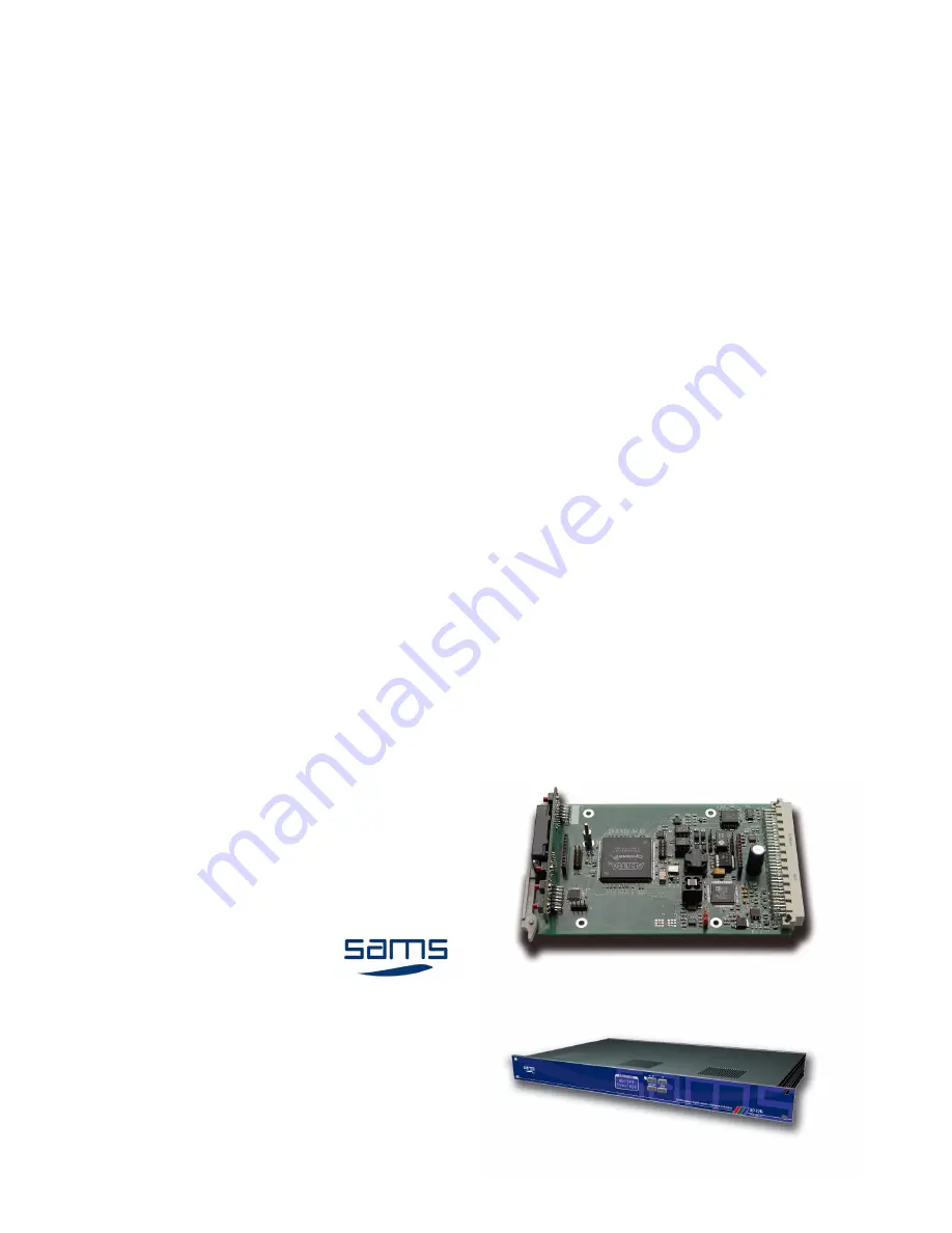
background image

AD-12(s)

Analog to digital converter

12/10 bit

- for SRU rack frame

- standalone

Copyright © 1999 - 2014 Sams elektronik d.o.o.

Published: 29. april 2011.

Updated: 07. july 2014.

Z10-3 edition 1

Code: 005.209

005.211

ENGLISH

Sams elektronik d.o.o.

48 Zivka Davidovica st.

11050 Belgrade

Serbia

Tel/Fax: +381 11 3806 253 

+381 11 2402 212

[email protected]

www.sams.rs

USER MANUAL FOR USE AND MAINTENANCE

Read the instructions before using the device.

Keep this manual for periodic usage.

Summary of Contents for AD-12

Page 1: ...29 april 2011 Updated 07 july 2014 Z10 3 edition 1 Code 005 209 005 211 ENGLISH Sams elektronik d o o 48 Zivka Davidovica st 11050 Belgrade Serbia Tel Fax 381 11 3806 253 381 11 2402 212 sams sams rs www sams rs USER MANUAL FOR USE AND MAINTENANCE Read the instructions before using the device Keep this manual for periodic usage ...

Page 2: ...rer servicer has not completed repair or replacement within a reasonable time or if the manufacturer servicer did not perform repair or replacement without significant inconvenience to the consumer 5 The consumer may not terminate the contract if the lack of conformity of the product is negligible 6 The product will function properly when used in accordance with the user manual 7 Period of servici...

Page 3: ...d with the device SAFETY WARNINGS FOR SRU RACK FRAME ELECTRICAL SHOCK HAZARD DO N OT O PEN CAUTION RIZIK OD S TRUJNOG UDARA NE O TVARATI DOK JE P OD N APONOM UPOZORENJE CLASS I DEVICE Grounding is connected to the chassis of the device The power supply is protected with fuse against overload DECLARATION OF CONFORMITY for product SRU RACK FRAME WITH POWER SUPPLY PSU 212 WITH CORRESPONDING MODULES A...

Page 4: ...e is equipped with a protective fuse in the power outlet Do not bypass fuse 12 Do not replace the fuse Replacement can be made by a person authorized by the manufacturer 13 Do not bend the power cord so that it can be damaged 14 Connect connectors as in the enclosed instructions Deviations from the allowed values predicted for the inputs and outputs of the device can cause severe damage and warran...

Page 5: ...DE 12 BLOCK DIAGRAM 13 INSTALLATION STANDALONE 13 THE DEVICE FUNCTIONS 14 ERRORS WITH CONNECTIVITY AND STATUS 14 FACTORY SETUP 15 MENU 15 MENU TREE 16 1 INPUT 17 2 HORIZONTAL VERTICAL BLANKING 17 3 HORIZONTAL POSITION 18 4 VERTICAL POSITION 18 5 ERROR MODE 19 6 COLOR LEVEL 19 7 Y OFFSET 20 8 Y LEVEL 20 9 CTI DNR 21 10 ANTI ALIAS 21 11 AGC MODE 22 12 SIGNAL TYPE 22 13 SETTINGS 23 NOTES 24 Page Desc...

Page 6: ...ized by Sams elektronik doo Any voluntarily opening device upgrading or servicing is strictly prohibited and is subject to warranty void and the possibility of injury Places for fastening PROCEDURES FOR SAFE USE OF THE DEVICE 1 If the device is not supplied with SRU rack frame remove the protective wrap from the device If the device is supplied with SRU rack frame remove the protective wrap from t...

Page 7: ...3D comb filter Processing delay 1line Integrated Three 54MHz Noise Shaped Video 12 bit AD converter and 4 x oversampling Integrated automatic gain control with adaptive peak white mode CTI chroma transient improvement DNR Digital Noise Reduction EDH processing Automatic YUV pixel timing adjustment Input signal presence detection Pass or broadcast test in the case of incorrect video input Integrate...

Page 8: ...mprovement DNR Digital Noise Reduction EDH processing Automatic YUV pixel timing adjustment Input signal presence detection Pass or broadcast test in the case of incorrect video input Integrated Test Generator Black Color Bar Easy setup with local control and LCD display OUTPUT PERFORMANCE Bit resolution 10 12bit processing Black offset Self adjusting H adjustment range 0 64μs in 37ηs steps V adju...

Page 9: ...U RACK FRAMES Make sure that the module is set to the correct place in relation to the back connector BEFORE INSTALLING OR REMOVING THE MODULE FROM SRU ALWAYS TURN OFF THE POWER Lock module with lever to the position NOTE NEVER PLACE MODULE TO PLACE OF THE POWER SUPPLY MODULE The label that indicates the place for power supply module FOR POWER SUPPLY ONLY WARNING ...

Page 10: ...elektronik d o o sams sams rs www sams rs 10 Converters 1 The module set between the guides not metal plate 2 Locking lever mount behind the groove 3 Push the lever to lock in an upright position The module is locked 1 2 3 ...

Page 11: ...UT C V Red AD 12 CVBS Y Y Green U Blue ADCV 8 SDI OUTPUT 1 SDI OUTPUT 2 ANALOG IN OPTIONS 1 CVBS 2 YC 3 YUV 4 RGB ANALOG IN ANALOG IN Fix the back connector with M2 5 screw Fix the back connector with M2 5 screw Be sure to install a protective pad before installing the back connectors BACK CONNECTORS ...

Page 12: ...ector with M2 5 screw 1 Mass 2 Power switch 3 The socket 4 Connections for back connectors Rear side view SRU REAR SIDE DO NOT INSERT SHARP METAL OBJECTS OR FINGERS INTO THE SPACE BEHIND THE POWER PANEL THE SIGN LIGHTNING IN A TRIANGLE IS TO ALERT THE USER TO THE PRESENCE OF LIFE THREATENING HIGH POWER LABEL IS PLACED NEXT TO POWER PANEL ...

Page 13: ... CVBS SDI OUTPUT 2 1 EXT REF Connect the power cord The device works only on AC 230 V 50 Hz Rear side Front side Connect all necessary connectors before the unit is turned on Connectors on rear side Analog inputs The device supports composite and component signal External rererence input The device supports the black burst generator as Sams MSG BB6 SDI outputs Turn on the device by pressing switch...

Page 14: ...s properly connected THE DEVICE FUNCTIONS 1 OK SAVE push button enters the submenu saving 2 STATUS LED GREEN the device is in normal mode RED flashing has a external reference but there is no input signal 3 Display 4 MENU BACK push button enter the menu from status mode exit from the submenu 5 UP push button Frame Freeze choose the value in the submenu freezes the image in the status mode 6 DOWN p...

Page 15: ...00μs V POS 000 lines ERROR MODE PASS ALL COLOUR LEVEL 100 Y OFFSET 100 Y LEVEL 100 CTI DNR OFF ANTI ALIAS OFF AGC MODE OFF SIGNAL TYPE STUDIO To set the device press the MENU BACK button Select the menu by pressing the UP DOWN keys On the selected menu press OK MENU Entering the menu for setting the device Sel Menu Input AD 12fs ...

Page 16: ... from 0 100 200 from 0 100 200 from 0 100 200 OFF OFF ON ON OFF STUDIO FAST SAT VCR SLOW SAVE MEM 1 4 PASS ALL LOAD MEM 1 4 BLACK FACTORY 75 COLOR BAR KILL OUT from 0 000μs to 63 963μs from 1 lines to 5 lines ADAPTIVE Sel Menu Input Sel Menu HV Blank Sel Menu Hor Pos Sel Menu Vert Pos Sel Menu Err Mode Sel Menu ColorLvl Sel Menu Y Offset Sel Menu Y Level Sel Menu Cti Dnr Sel Menu A Alias Sel Menu ...

Page 17: ...on press the MENU BACK button Option is temporarily saved Menu Input Menu HV Blank Sel Menu Input AD 12fs Sel Menu HV Blank AD 12fs 2 HORIZONTAL VERTICAL BLANKING This menu is used for pass remove information that is contained in the horizontal and vertical blanking Choose one of options PASS ALL allow all the information contained in the horizontal embedded audio and vertical blanking from 6 to 2...

Page 18: ... setting is 1 lines Select an option by pressing the UP DOWN keys Menu Horisontal position Sel Menu Hor Pos AD 12fs 3 HORIZONTAL POSITION This menu is used to adjust the horizontal phase of the output video signal Horizontal phase shifts in the intervals 37ns half of one pixel up to a maximum of one video line 63 963μs During the change in value it may cause short term image disturbance in monitor...

Page 19: ...ode AD 12fs 5 ERROR MODE This menu is used to set how the product behaves during a fault in the signal Select an option PASS ALL device pass signal no matter how bad signal is BLACK the unit will generate a black image due to poor incoming video signal 75 COLOR BAR the unit will generate a color bar due to poor incoming video signal KILL OUT device will cancel the signal at the output due to poor ...

Page 20: ...offset Menu Y level Sel Menu Y Offset AD 12fs Sel Menu Y Level AD 12fs 7 Y OFFSET This menu is used to adjust the brightness Control is allowed in a range of 0 to 200 The factory setting is 100 Select by pressing the UP DOWN keys This menu is used to adjust the contrast This is achievable by scaling Y luma signals controlled by the user Control is allowed in a range of 0 to 200 The factory setting...

Page 21: ...u A Alias AD 12fs 9 CTI DNR 10 ANTI ALIAS This menu is used to activate deactivate the optional Digital Noise Reduction and Chroma Transient Impovement Options are ON and OFF The default setting is OFF Select by pressing the UP DOWN keys In digital signal processing this option reduces distortion known as aliasing This is an ideal tool for removing the major frequency components of the signal than...

Page 22: ... is STUDIO Select an option by pressing the UP DOWN keys NOTE When using a TV VCR mode then you can have irregular signals at input which may cause the illegal values of digital output signal Once you have selected the option press the MENU BACK button Option is temporarily saved Menu Signal Type Sel Menu Sig Type AD 12fs Once you have selected the option press the MENU BACK button Option is tempo...

Page 23: ... record 4 different settings After selecting a bank press OK SAVE The display will print SAVED If you want to stay in this menu press the UP DOWN keys and to exit the MENU BACK button In this menu there are options LoadMem1 LoadMem2 LoadMem3 and LoadMem4 or options to load settings After selecting a bank press OK SAVE The display will print LOADED If you want to stay in this menu press the UP DOWN...

Page 24: ...ADC elektronik Sams elektronik d o o sams sams rs www sams rs 24 Converters NOTES ...

Reviews: