Sailor C4900, Installation Manual
The Sailor C4900 is a cutting-edge communication device designed for seamless maritime operations. Ensure hassle-free set-up and configuration with our comprehensive Installation Manual. You can easily download this essential manual for free from our website, providing step-by-step instructions to optimize your experience with the Sailor C4900.
Share
Download


Reviews:
No comments
Related manuals for C4900

P70
Brand: Raymarine Pages: 70

DMR109
Brand: Makita Pages: 12

MGM 450
Brand: Ericsson Pages: 70

BP9
Brand: Blaupunkt Pages: 28

Atlas PT
Brand: Raveon Pages: 43

ROCKET 2AC PRISM
Brand: Ubiquiti Pages: 28

10041150
Brand: auna Pages: 76

JL-725
Brand: jWIN Pages: 3

UK25 LTD ST
Brand: Cobra Pages: 21

MC522BC LCD Microphone
Brand: GME Pages: 24

X-tra Talk LXT118 Series
Brand: Midland Pages: 12

VXD-R70
Brand: Vertex Standard Pages: 24
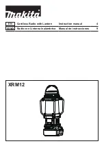
XRM12
Brand: Makita Pages: 14
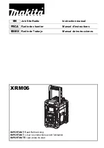
XRM06
Brand: Makita Pages: 32

XRM10
Brand: Makita Pages: 36
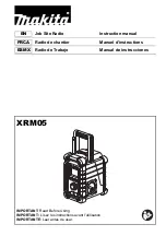
XRM05
Brand: Makita Pages: 60
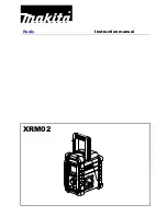
XRM02
Brand: Makita Pages: 10

i-Q350
Brand: IDENTEC SOLUTIONS Pages: 11


