Saab 32 026 005, Installation Instructions Manual
The Saab 32 026 005 Installation Instructions Manual is a comprehensive guide that provides step-by-step instructions for installing and configuring your Saab 32 026 005 product. This essential manual can be downloaded for free from our website, ensuring you have easy access to the information you need.
Share
Download


Reviews:
No comments
Related manuals for 32 026 005

SmartDiag2GO GD201-O
Brand: OCTO Pages: 5

SD 13R07-5
Brand: FORM FIT Pages: 2

Edge Flush Rail
Brand: Thule Pages: 12

1511
Brand: Thule Pages: 8

2004 S2000
Brand: Honda Pages: 208

2008 MX-5 Miata
Brand: Mazda Pages: 400
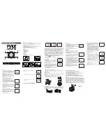
PHRM36
Brand: Pyle Pages: 1

PORTAGE 819
Brand: Thule Pages: 12

DBALL2-HK7
Brand: Xpresskit Pages: 18

1061-1-011
Brand: Thule Pages: 3

88365
Brand: Air Lift Pages: 28

DAS400
Brand: Dolphin Pages: 16

SWGH3
Brand: Streetwize Pages: 4

TRANSIT CUSTOM
Brand: Ford Pages: 15

08L04-SZA-100
Brand: Honda Pages: 3

CRV 2015
Brand: Honda Pages: 253

2018 yaris
Brand: Toyota Pages: 11

28-21030
Brand: Westin Pages: 3


