

MCT88M-IO Installation Manual
2019-10-02
1/2
Roger Access Control System
MCT88M-IO Installation Manual
Firmware version: 1.0.2.97 and newer
Document version: Rev. F
This document contains minimum information that is necessary for initial setup
and installation of the device. The detailed description of configuration
parameters and functionalities is specified in respective Operating manual
available at
I
NTRODUCTION
The terminal is designed to operate in RACS 5 system as peripheral device
connected to RS485 bus of MC16 access controller. Alternatively the device can
communicate with virtual controller via Ethernet (LAN) and operate as PoS
terminal or assets management terminal. Factory new terminal is configured with
default settings including ID=100 address. Before connecting to MC16 controller,
the device should be assigned with unoccupied address in range of 100-115.
Programming of other parameters depends on the individual requirements and is
not obligatory. Configuration of the terminal with RogerVDM requires RUD-1
interface.
C
ONFIGURATION WITH
R
OGER
VDM
PROGRAM
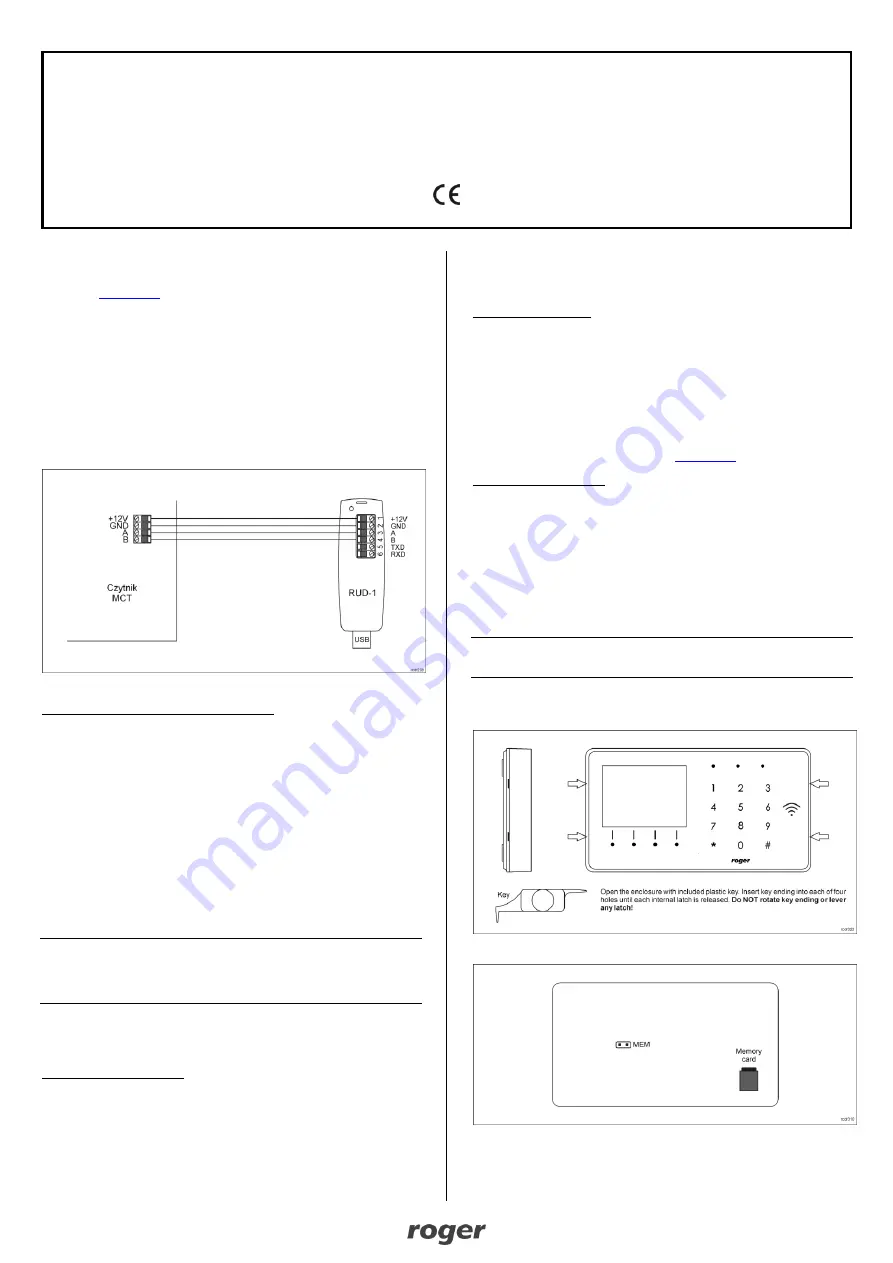
Fig. 1 Connection of the terminal to RUD-1 interface for configuration
Programming procedure with RogerVDM software:
1. Place jumper on MEM contacts (fig. 3).
2. Connect the device to RUD-1 interface according to fig. 1 and connect RUD-
1 to computer’s USB port. The terminal will display CONFIG MODE text and
orange LED SYSTEM will pulsate.
3. Start RogerVDM program, select
MCT
device,
v1.0
firmware version,
RS485
communication channel and serial port with RUD-1 interface.
4. Click
Connect,
the program will establish connection and will automatically
display
Configuration
tab.
5. Select RS485 communication interface and specify unoccupied RS485
address in range of 100-115 or select Ethernet communication interface and
specify IP address. Configure other low level configuration parameters as
needed.
6. Click
Send to Device
to update the configuration of device.
7. Optionally make a backup by clicking
Send to File…
and saving settings to
file on disk.
8. Remove jumper from MEM contacts and disconnect device from RUD-1
interface.
Note: If the USB port does not offer enough current then supply the terminal from
external 12VDC PSU min. 200mA power output.
Note: Do not read any cards nor press keypad when device is configured with
RogerVDM.
M
ANUAL ADDRESSING
Manual addressing procedure enables configuration of new RS485 address with
all other settings unchanged.
Manual addressing procedure:
1. Remove all connections from A and B lines.
2. Place jumper on MEM contacts (fig. 3).
3. Restart the device (switch power supply off and on). The terminal will display
CONFIG MODE text and orange LED SYSTEM will pulsate.
4. Enter 3 digits of RS485 address in range of 100-115 with keypad.
5. Wait till device starts to emit continuous sound.
6. Remove jumper from MEM contacts and restart the device.
M
EMORY RESET PROCEDURE
Memory reset procedure resets all settings to factory default ones including
ID=100 address.
Memory reset procedure:
1. Remove all connections from A and B lines.
2. Place jumper on MEM contacts (fig. 15).
3. Restart the device (switch power supply off and on). The terminal will display
CONFIG MODE text and orange LED SYSTEM will pulsate.
4. Press [*] or read any MIFARE card 11 times.
5. Wait till device confirms reset with continuous sound.
6. Remove jumper from MEM contacts and restart the device.
F
IRMWARE UPDATE
New firmware can be uploaded to the terminal by means of included memory
card. The latest firmware file is available at
Firmware update procedure:
1. Disconnect power supply.
2. Press and remove memory card from socket (fig. 3).
3. Using memory card reader, copy main firmware (*.frg) to the card and
rename it as FW.BUF. Copy additional firmware (*.cyacd) for keypad and
BLE and rename it as KBDFW.CYA.
4. Insert the card into socket.
5. Connect power supply and wait till device completes starting procedure. The
progress of additional firmware uploading is shown on the display.
6. Disconnect power supply when additional firmware KBD is 100% uploaded.
7. Connect power supply and wait till device completes starting procedure.
8. Start RogerVDM and perform low level configuration.
Note: During the firmware update process, it is necessary to ensure continuous
and stable power supply for the device. If interrupted the device may require
repair by Roger.
A
PPENDIX
Fig. 2 Enclosure disassembly
Fig. 3 Service contact and memory card


