Riva RTS650, Installation Manual
The Riva RTS650 Installation Manual is a comprehensive and user-friendly guide designed to assist you in setting up and utilizing your Riva RTS650 effectively. This manual is available for download absolutely free of charge from our website, ensuring hassle-free access to valuable instructions and key insights for your convenience.
Share
Download


Reviews:
No comments
Related manuals for RTS650

P3
Brand: Papago Pages: 82
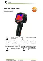
testo 868s
Brand: ICS Schneider Messtechnik Pages: 42

DashCam C2 Pro
Brand: Roav Pages: 11

S40 Pro
Brand: AEE Pages: 18

Night
Brand: Xblitz Pages: 17

BT58190
Brand: Yada Pages: 28

DVR-C310R
Brand: Alpine Pages: 39

T-CAM 380 P Series
Brand: INFRARED CAMERAS Pages: 49

ME200S-SH
Brand: Canon Pages: 80
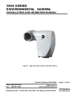
3960 Series
Brand: IVIEW Pages: 28

UNISON
Brand: IVIEW Pages: 30

C326
Brand: Spedal Pages: 9

HTJ-DVR2
Brand: HTJ AUTO Pages: 11

HT-A3
Brand: HTI Pages: 8

Z3D
Brand: Z-EDGE Pages: 44

T5 Pro
Brand: THIEYE Pages: 149

CC 104
Brand: Gogen Pages: 25

VC-715
Brand: Vakoss Pages: 15


