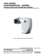
background image

Phone: 858-277-6700

www.cohu-cameras.com

Cohu Electronics • 3912 Calle Fortunada • San Diego, CA 92123-1827

Fax:     858-277-0221

[email protected]

3960 SERIES
ENVIRONMENTAL  CAMERA

INSTALLATION AND OPERATION MANUAL

Technical Manual 6X-1050a

August 11, 2005

Figure 1.  High Performance Environmental Camera

Summary of Contents for 3960 Series

Page 1: ...u Electronics 3912 Calle Fortunada San Diego CA 92123 1827 Fax 858 277 0221 info cohu com 3960 SERIES ENVIRONMENTAL CAMERA INSTALLATION AND OPERATION MANUAL Technical Manual 6X 1050a August 11 2005 Figure 1 High Performance Environmental Camera ...

Page 2: ... B C and D 16 17 D im ensions 3960 Standard B ase 19 18 D im ensions Optional Large B ase 19 19 A bout W inMP C GUI S creen 20 20 C ohu W inMP C Home S creen 21 21 W inM P C S etup S creen 22 22 D im ensions Wall Mount A rm 24 23 D im ensions P ole M ount 25 24 D im ensions C orner Mount 26 25 D im ensions P arapet Mount 27 26 Installed P arapet M ount 27 TABLE TITLE PAGE 1 Specifications 4 2 Moun...

Page 3: ... a system after setup by WinMPC either Cohu system software or some common third party software can be used depend ing on the requirements of the installation 1 1 2 Cohu System Control Software The 3960 can be operated by either the Cohu Cams or NetCams software or by a variety of other common third party software protocols Not all features may be available with some of these third party protocols...

Page 4: ...an be stored to file for easy duplication Inverted Operation Can be mounted in an inverted position software compensates for inversion Vibration less lens Sine vibration from 5 to 30 Hz 1 2 g 3 axis one hour Shock Up to 10 g s 11 ms in any axis under nonoperating conditions Air Contaminants Withstands exposure to sand dust fungus and salt atmospheres per MIL E 5400T paragraph 3 2 24 7 3 2 24 8 and...

Page 5: ...ations continued All electrical connections are made via a 34 inch pigtail cable permanently attached to the bottom of the 3960 base A connector with positions for 16 pins is connected to this cable to provide all electrical connections Only 11 of these pin loca tions are used A Schrader valve figure 14 the car tire type air valve on the left on the rear panel provides for pressurizing the housing...

Page 6: ...arapet mount assembly Note that the LPEDD large pedestal base does not mount to any of the accessories listed in this table This adapter plate has hole patterns typically used by other accessory mounts used with cameras Table 2 Mounting Configurations Figure 2 Model Number Interpretation Diagram SERIES POWER DSP Color Camera Pressurized Housing Sunshield 4 24 V ac input power 5 115 V ac input powe...

Page 7: ...tterns on a larger diameter A 3960 can be mounted in any one of six mechanical configurations depending on the mount ing accessories supplied The model number defines the mounting equipment supplied as part of the 3960 Table 2 shows the mounting items sup plied for each of the mounting configurations avail able with a 3960 2 0 INSTALLATION This section covers the general requirements of installing...

Page 8: ...static discharge Use appropriate static con trol methods when working inside the 3960 Components used in modern electronic equip ment especially solid state devices are susceptible to damage from static discharge The relative sus ceptibility to damage for semiconductors varies from low with TTL to high with CMOS Most other semi conductors fall between TTL and CMOS in suscepti bility to static disc...

Page 9: ... A mating connector is supplied for making system interconnections This connector should not be attached to the system cable until it is known that If the optional large mounting base is ordered LPEDD option it will be supplied with four 1 4 20 x 3 4 mounting screws If the plate is factory installed these screws will be used for that installation and not supplied as loose parts 2 4 Equipment Requi...

Page 10: ...gure 15 This panel is typically located in a nearby equipment cabinet It is used when an on site local control panel is desired for setup and maintenance operations This panel typically is installed in a weatherproof cabinet located near the 3960 instal lation location This optional panel can control some functions of the 3960 without use of a local laptop PC running WinMPC But a front panel BNC c...

Page 11: ...igure 8 related to mounting the 3960 The 3960 can be optioned for six different mounting configurations 1 Direct mounting to the base plate on the 3960 See section 4 1 for details about this standard mount ing base 2 Mounting to a second larger circular mounting base which then mounts to a suitable surface See section 4 2 for mounting with this option 3 Wall Mount Arm for direct mounting to a suit...

Page 12: ...edure It is important to carefully plan for all cable routing before starting an installation In some situations cable will have to be pulled through conduit or other narrow places before adding a connector to the end of a system cable Any through wall holes may require weatherproofing Installing the 3960 is straightforward It is only necessary to mount the 3960 to a suitable base mate the cable c...

Page 13: ...ground video 3 ground data 4 TX 5 TX 6 RX 7 RX 8 nc 9 nc 10 nc 11 nc 12 115 V ac line high hot 13 115 V ac neutral low 14 shield overall cable 15 ground ac 16 nc nc designates not connected not used Table 6 Pin Functions 115 V ac Camera Connector Figure 12 Test Cable CTC 30 115 V ac ...

Page 14: ... CTC 35 24 V ac Table 7 Pin Functions 24 V ac Camera Connector PIN FUNCTION 1 video 75 ohm 2 ground video 3 ground data 4 TX 5 TX 6 RX 7 RX 8 nc 9 nc 10 nc 11 nc 12 nc 13 24 V ac low 14 shield overall cable 15 ground ac 16 24 V ac high nc designates not connected not used ...

Page 15: ...dded to replenish the lost nitrogen This valve should be manually lifted off its seat or pushed slightly to the side when it is desired to flow dry nitrogen through the camera to purge moisture laden atmospheric air from the camera module Regularly applying pressure above 5 to 8 psig 35 to 55 kPa may cause seals to weaken and leak 2 8 2 16 pin Connector This connector is attached to the 34 inch 86...

Page 16: ...16 6X 1050a 3960 CAMERA INSTALLATION AND OPERATION Figure 16 Cable Schematics Type CA 297 A and B Versions C and D versions and Notes on next page ...

Page 17: ...7 009 1310307 103 clamp 1310308 002 6 contact 1310308 008 5 contact B 1310307 009 1310307 103 clamp 1310308 002 6 contact 1310212 004 BNC 1310308 008 5 contact C 1310307 009 1310307 103 clamp 1310308 002 6 contact 1310212 004 BNC 1310308 008 5 contact D 1310307 009 1310307 103 clamp 1310308 002 6 contact 1310306 010 Amp 1310307 103 clamp 1310308 001 6 contact 1310308 008 5 contact 1310308 007 5 co...

Page 18: ...he RS 232 BNC connector on the front of the panel for communications with the 3960 The LOCAL REMOTE switch on the 9300 must be set to LOCAL to perform this local control The model 9300 local control panel can be programmed for a site address That address is used for the site address not the address of the 3960 The system cable plugs into the 9300 and a second cable then interconnects between the 9...

Page 19: ...N AND OPERATION Figure 17 Dimensions 3960 Standard Base Permanent Part of 3960 Figure 18 Dimensions Optional Large Base attaches to base above Fastens to Standard Base Above Four 1 4 20 x 3 4 Flathead Screws Included Cohu P N 0310010 093 ...

Page 20: ...to MPC Receiver d At the Camera area of the window i Select Day Night default ii Under Video select NTSC or PAL as appropri ate e Under the Pan Tilt area of the window i Select Var Speed P T default ii Select a Max Pan Speed of 15 default iii Select a Max Tilt Speed of 15 default f Under the Pan Tilt Background area select any desired image type for the center pan tilt area of the home page g Unde...

Page 21: ...lished with the 3960 various functions should be tested to verify proper operation Use the Win MPC interface to perform tests and setups Check all the Momentary functions zoom focus iris color and integration Latch commands also should be tested 3960 power lens fast manual iris and color balance Several presets should be set and then re established to verify their operation After presets are estab...

Page 22: ...nt a 3960 it is impor tant to have either pre installed the system cable or to have verified that the cable can be routed to the location of the mounting assembly This often requires pulling cable through conduit and other tight places It is also necessary to plan for weather proofing any through wall holes 4 1 PEDESTAL MOUNT INSTALLATION SMALL BASE PLATE This is the simplest configuration Only th...

Page 23: ...apter plate flat for placing on an existing on site mounting base These holes are on the 4 750 diameter pattern If site supplied flathead screws are used they must not protrude through the standard base plate by more than 0 1 inch More than this would jam into the 3960 housing This optional base has two four hole patterns for mounting to a pedestal or other type mount One pattern is on a 7 inch di...

Page 24: ...ole so that the full cable weight is not supported solely at the top A pole mount installation is similar to the wall mount installation except that the arm fastens to a pole mount bracket instead of directly to a wall 4 Install a weather tight gasket between the arm and the surface of the wall if this is required 5 Route the 3960 pigtail cable down into the arm and out the back Note that plastic ...

Page 25: ...he arm adapter plate and secure it with the hardware 7 Connect the pigtail connector to the system cable connector 8 Pull the system cable back so the arm can be slid over the pole mount threaded studs 9 Install lock washers and nuts to secure the arm to the bracket 10 Verify that the 3960 will have a full range of movement without striking any nearby structures 11 Refer to section 3 to set up and...

Page 26: ...without striking any nearby structures 11 Refer to section 3 to set up and check out the 3960 4 6 PARAPET MOUNT INSTALLATION Figure 7 shows the parapet mount A parapet is the wall that rises above the flat roof of a typical commercial building This mount typically attaches inside this raised wall and the vertical mounting surface faces out toward the surrounding area The wall mount arm bolts direc...

Page 27: ...apet mount threaded studs 9 Install lock washers and nuts to secure the arm to the bracket 10 Verify that the 3960 will have a full range of movement without striking any nearby structures 11 Refer to section 3 to set up and check out the 3960 end Figure 25 Dimensions Parapet Mount Figure 26 Installed Parapet Mount ...

Page 28: ...elivery shall be repaired without charge This warranty does not extend to Cohu equipment subjected to misuse accident neglect improper application or repaired or altered by other than Cohu or those authorized by Cohu in writing Cameras utilizing extended IR sensors are not warranted for use in areas of elevated levels of cosmic radiation Television image pickup tubes image intensifiers lenses and ...

Reviews: