manualshive.com logo in svg
background image

RISO INTERNATIONAL GROUP

RISO KAGAKU CORPORATION (JAPAN)

RISO DEUTSCHLAND GMBH (GERMANY)

RISO, INC. (U.S.A.)

RISO FRANCE (FRANCE)

RISO EUROPE LIMITED (U.K.)

RISO IBERICA (SPAIN)

RISO HONG KONG (HONG KONG)

RISO CANADA (CANADA)

RISO UK (U.K.)

ZHUHAI RISO TECHNOLOGY (CHINA)

RISO THAILAND LIMITED (THAILAND)

RISO AFRICA (SOUTH AFRICA)

RISOGRAPH ITALIA (ITALY)

Copyright :  2002  Riso Kagaku Corporation
All Rights Reserved. This Technical Manual was prepared and
written for the exclusive use of RISO International Group Certified
Dealers. Reproduction and/or transmittal of this material in any form
or by any means, including photocopying or recording of the
information is strictly prohibited without the consent of a member of
RISO International Group.

VERSION

FEBRUARY 2002

V8000

SERIES

TECHNICAL MANUAL

Содержание V8000 Series

Страница 1: ...ILAND RISO AFRICA SOUTH AFRICA RISOGRAPH ITALIA ITALY Copyright 2002 Riso Kagaku Corporation All Rights Reserved This Technical Manual was prepared and written for the exclusive use of RISO International Group Certified Dealers Reproductionand ortransmittalofthismaterialinanyform or by any means including photocopying or recording of the informationisstrictlyprohibitedwithouttheconsentofamemberof ...

Страница 2: ...w 2 5 CHAPTER 3 MAIN DRIVE SECTION Mechanism 3 2 1 Main Drive Section Rotating Mechanism 3 2 2 Main Motor Safety Mechanism 3 4 3 Paper Drum Rotation Position 3 6 4 Low Temperature Printing Speed Limit 3 6 Disassembly 3 7 1 Removing the Main Cover Ass y 3 7 2 Removing the Paper Feed Intermediate Gear Pump Gear and Guide Gear 3 8 3 Removing the Main Motor Unit 3 11 CHAPTER 4 FIRST PAPER FEED SECTION...

Страница 3: ...ustment 4 20 1 Paper Width Potentiometer Adjustment 4 20 2 Elevator Upper Limit Sensor A Position Adjustment 4 20 3 Paper Limit Detection Plate Attachment 4 21 4 Stripper Adjustment 4 22 5 Position of Multiple Paper Feed Switch 4 23 CHAPTER 5 SECOND PAPER FEED SECTION Mechanism 5 2 1 Second Paper Feed Mechanism 5 2 2 Paper Pass Guide Mechanism 5 2 Disassembly 5 3 1 Removing the Paper Pass Guide 5 ...

Страница 4: ...per Receiving Tray Mechanism 7 3 Disassembly 7 4 1 Removing the Paper Receiving Tray 7 4 2 Removing the Paper Ejection Pinch Unit 7 5 3 Removing the Paper Receiving Tray Support Ass y 7 5 4 Removing the Paper Ejection Cover Ass y 7 6 5 Removing the Paper Ejection Sensor Send 7 6 6 Removing the Paper Ejection Roller Unit 7 7 7 Removing the Paper Ejection Motor 7 7 8 Removing the Paper Ejection Limi...

Страница 5: ... Removing the Ink Volume Detection Sensor Receive 8 9 4 Removing the Ink Volume Detection Sensor Send Ass y 8 10 5 Removing the Inner Pressure Clutch 8 11 6 Removing the Horizontal Pulse Motor Ass y 8 12 7 Removing the Ink Pump Ass y 8 13 8 Removing the Pressure Control Motor 8 14 9 Removing the Ink Sensor PCB 8 16 10 Removing the Clamp Plate Base Ass y 8 18 11 Removing the Inner Pressure Roller U...

Страница 6: ...anism 10 2 1 Mechanism Outline 10 2 2 Print Drum Positioni A Movement 10 4 3 Clamp Unit Engaged and Disengaged Position 10 5 4 Clamp Unit Initial Position 10 5 5 Angular Sensors 10 5 6 Clamp Plate Movement 10 6 Disassembly 10 7 1 Removing the Clamp Unit Same for 1st and 2nd 10 7 2 Removing the Angular Sensor PCB 10 7 3 Removing the Clamp Slide HP Sensor and Clamp Slide Sensor 10 8 4 Removing the C...

Страница 7: ...Disposal Plate 11 12 13 Removing the Disposal Plate Shaft 11 13 14 Removing the Master Compression Motor 11 14 15 Removing the Master Compression Plate 11 15 16 Removing the Disposal Box Safety SW 11 17 17 Removing the 2nd Master Disposal Unit 11 18 18 Removing Vertical Transport Roller G and the Master Disposal Belt 2nd Master Disposal Unit 11 19 19 Removing Vertical Transport Roller J 2nd Master...

Страница 8: ... and Shrinkage Adjustment 13 19 4 AF Original IN Sensor Sensitivity Adjustment 13 20 CHAPTER 14 MASTER MAKING SECTION Mechanism 14 2 1 Basic Construction of the Master Making Section 14 2 2 Master Making Unit Shifting Mechanism 14 2 3 TPH Elevation Mechanism 14 2 4 Master Set Mechanism 14 2 5 Master Loading 14 2 6 Master Cutting Mechanism 14 3 Disassembly 14 4 1 Removing the Master Volume Detectio...

Страница 9: ...TIMING CHARTS This chapter is not completed CHAPTER 16 PANEL MESSAGES 1 Explanation of Panel Messages 16 2 1 Error Code display 16 2 2 Error Type display 16 2 3 Error Point display 16 2 2 List of Error Types 16 3 T Serviceman Call error 16 3 A Jam error 16 3 B Option error 16 4 C Consumable error 16 4 D Set Check error 16 4 E Warning Serviceman Call 16 4 F Warning Other 16 4 3 Detailed List of Pan...

Страница 10: ...er Disposal Test Mode 17 14 7 Paper Feed Eject Test Mode 17 16 8 Print Drum Test Mode 17 20 9 Printing Test Mode 17 25 10 Accessories 1 Test Mode 17 27 11 Factory Mode Test Mode 17 30 CHAPTER 18 FUNCTIONS Function Settings Sub Screen 18 2 1 Configuration 18 2 1 Selections 18 2 2 Memory Mode Memory 18 2 3 Programs Program Printing Memory 18 2 4 Other Settings Functions List 18 3 5 Other Settings Pr...

Страница 11: ... 3 1 RIPU PCB Image PCB 20 6 2 4 1 MCTL PCB Mechanical Control PCB 1 of 3 20 7 2 4 2 MCTL PCB Mechanical Control PCB 2 of 3 20 8 2 4 3 MCTL PCB Mechanical Control PCB 3 of 3 20 9 2 5 1 Main Drive PCB 20 10 2 6 1 Side Drive PCB 1 20 11 2 7 1 Side Drive PCB 2 20 12 2 8 1 Master Making PCB 20 13 2 9 1 TPH Power PCB 20 14 2 10 1 Drum PCB 1 20 15 2 11 1 Drum PCB 2 20 16 2 12 1 Panel Unit 20 17 INDEX i ...

Страница 12: ...1 CHAPTER 1 MAINTENANCE Contents 1 Preface 1 2 CAUTION 1 3 WARNING 1 4 2 Work Precautions 1 5 3 JIGs 1 8 4 Installation Procedure 1 11 5 Leveling the Machine on the Floor 1 15 6 Exterior Cover Removal 1 19 ...

Страница 13: ...000 series This manual also provides procedures for removing and installing major components Following these procedures will minimize machine malfunctions The information will also increase technical represen tatives awareness and experience regarding repairs necessary to insure end user satisfaction ...

Страница 14: ...disassemble the battery or press it into deformation DANGER If you disassemble the battery the gas pouring out of the inside may hurt your throat or the negative lithium may heat up into fire If the battery is pressed into deformation the liquid inside may leak out of the sealed part or the battery may be short circuited inside an explode 4 Never fail to keep the battery out of reach of children I...

Страница 15: ...rs or when connecting a Meter 2 WARNING The back light tube of LCD of the Control Panel on this Model contains mercury which must be recycled or disposed of as hazardous waste 3 Always connect electrical connectors firmly I To avoid electrical failure The connectors must be connected firmly together and onto the PCBs Press on the ends of the connectors and then on the middle to ensure a firm fit I...

Страница 16: ...d Installation Unless specified otherwise perform the removal proce dures in reverse during assembly and installation In cases where protrusions or holes are provided to assist in positioning parts use them for accurate positioning and securing Protrusions and holes for positioning parts Half pierce section Tools Using tools other than those specified can lead to injury or damage screws and parts ...

Страница 17: ...roswitchesmaybedividedbetweennor mallyopen NO typesandnormallyclosed NC types With an NO connection an internal con tact is connected when the switch actua tor is pressed With an NC connection an internal con tact is disconnected when the switch ac tuator is pressed Magnetic lead switches are switches in which an internal contact is connected in reaction to the magnetic force of a magnet Sensor ty...

Страница 18: ...ation allowed 4 Those with radiant heat sources and any locations in the direct path of air from air condition ers heaters 5 Any poorly ventilated location 6 Dusty atmosphere 7 Any tilted location Levelness of the floor Within 2 degrees incline and within 3mm difference in floor height Electrical connection Plug the plug securely into the socket so that there is no problem with the contact in the ...

Страница 19: ...aft JIG 016 16141 003 8 mm dia x 160 mm shaft JIG 2 pieces required 022 18402 006 8 mm diameter long shaft JIG 022 76001 003 Squeegee Gap Adjustment Shaft JIG 015 36311 005 Squeegee Gap Gauge JIG 022 16714 000 Drum Manual Rotation Knob S0101 S0102 S0103 S0104 S0105 S0106 ...

Страница 20: ... one unit with one of the weight facing the other way 030 90010 050 LED Unit Instructions for using the LED Unit 1 Remove the Rear Cover 2 Plug the connector of the LED Unit into connector CN20 of the MCTL PCB 3 Choose the display sheet for V8000 on the LED Unit 4 Look at the LED display of the LED Unit to check the condition of the machine S0107 S0108 P0109 P0110 S0111 ...

Страница 21: ...hould make one straight line Tighten the two screws 2 Swing open the plate indicated as C on above sketch until the pivot portion of the plate hits firmly against the plate indicated as A Tighten the two screws 3 Tie string on the groove pointed out as D on above sketch at the tail of plate C and tie a piece of weight on the other end of the string Refer to page 1 15 Note The string diameter of ab...

Страница 22: ... this unit 1 Side cover 1 pc 2 Unit cover F 1 pc 3 Unit cover R 1 pc 4 Front door L 1 pc 5 Front door R 1 pc 6 Adjustment foot 2 pcs 7 Instruction label 1 pc 8 Blind seal 1 pc 9 Screws 1 set Item to be Used Use the following item in this package 1 Insert the Front door R into the rail on the lower right part of the printer from upward 2 Unlock the rail on the upper part of the Front door R and ext...

Страница 23: ... Unit cover F 6 Remove the plate which locks the Scanner table Lock plate 7 Open the Scanner table and remove three lock plates which secure the Master roll cover 8 Replace the bolts removed in the previous step Lock plates Bolt Bolt 4 Secure the rail with binding screws which are coated with blue gum M4x6 2pcs 5 Secure the Front door L same as the Front door R steps 1 through 4 ...

Страница 24: ...et Shock absorbing sheets 12 Open the Paper receiving tray and remove the Shock absorbing sheets 13 Remove the carrying handle catchers in the Paper receiving area Master loading unit Paper receiving tray Carrying handle catchers 14 Remove the carrying handle catchers in the Paper feed area Carrying handle catchers 3 ...

Страница 25: ...e of levels between the front and rear frame of the printer using the specified jig For the description about the jig and the operation procedure refer to the technical manual 20 Insert the Adjustment feet under the front door to fit the caster bases as illustrated 21 Turn the lower nuts on the Adjustment feet clockwise until the feet reach the floor 22 Using the jig adjust the levels of the Adjus...

Страница 26: ...eet against the machine frame is pointed out by thick arrow marks on one of the photographs below 3 Let a string with a weight tied on one end hang on the Leveling jig as shown on the photographs below The string should not touch the metal scale at the bottom of the Leveling jig to allow free hanging of the string P0129 P0130 P0131 Scanner table Machine frame rear Leveling jig Leveling jig Levelin...

Страница 27: ... against the scale P0134 P0133 P0132 P0135 Front side of the machine 5 On the front of the machine remove four screws holding the Operation Panel refer to arrow marks on the photograph below Then remove one screw at the back of the Operation Panel on the paper receiving side String in front of the scale Operation panel Operation panel String at back of the scale The string should hang free from th...

Страница 28: ...e the Leveling jig from the rear machine frame and mount it on the front machine frame in the same manner as done on the rear machine frame 8 Read the scale at the bottom of the jig in the same way as done for the rear of the machine 9 The difference in the scale reading between the rear and front should be within 0 5 mm Operation panel Machine frame front Machine frame front Leveling jig ...

Страница 29: ...ise the machine until the rear and front of the machine is leveled the difference in the scale reading is within 0 5 mm between the front and rear The Height adjuster is raised or lowered by turning the bottom nut 12 After adjusting the levelness lock the position by turning and bringing the center nut tightly against the top nut S0113 S0114 Locking the Height adjuster Rotate the center nut tight ...

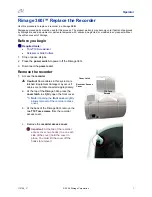
Страница 30: ... 1 19 CHAPTER 1 MAINTENANCE 4 Removing Exterior Covers Rear cover Rear cover P0112 ...

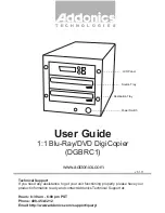
Страница 31: ... 1 20 CHAPTER 1 MAINTENANCE Front doors L R Front door R Front door L P0113 P0114 P0115 P0116 ...

Страница 32: ... 1 21 CHAPTER 1 MAINTENANCE Upper interior cover Lower interior cover Upper interior cover Lower interior cover P0117 P0118 ...

Страница 33: ...2 CHAPTER 1 MAINTENANCE Master disposal exterior cover F cover L Rear left cover FB left cover Paper feed cover Master disposal exterior cover F cover L Rear left cover FB left cover Paper feed cover P0119 ...

Страница 34: ...ster making unit cover Master disposal exterior cover F cover R Rear right cover FB right cover FB handle cover Master making unit cover Master disposal exterior cover F cover R Rear right cover FB right cover FB handle cover P0120 ...

Страница 35: ...y slide the scanner table in the reverse direction and remove the hidden screws FB lock plate front To remove the FB right and FB front covers slide the scanner table insert a screwdriver through the hole marked by the arrow in the picture and remove the screws FB safety SW Assy P0121 P0122 P0123 P0124 P0125 ...

Страница 36: ... 1 25 CHAPTER 1 MAINTENANCE Scanner table cover FB front cover FB rear cover Scanner table cover FB front cover FB rear cover Scanner table cover hinges Original alignment sheet P0126 P0127 ...

Страница 37: ... 2 1 CHAPTER 2 MACHINE OVERVIEW Contents 1 Features 2 2 2 Specifications 2 3 3 Product Configuration 2 4 4 Schematic Cross Sectional View 2 5 ...

Страница 38: ...ts with combined two color printing for dramatically improved image quality compared to previous single color tones Network compatible with a monitoring function to track operations on screen The RISO V8000 can be networked for high speed high quality output of document data created on PCs The monitoring function allows monitoring of RISO V8000 status e g standby in use paper status paper size con...

Страница 39: ...ct touch control panel Dot screening 4 patterns Print speed density control Scanning contrast control auto manual Photo contrast enhancement Duo processing Tone curve adjustment Bound document processing Mirror image print Background watermark printing Multi up printing including ticket Programmed printing 2 types Print job memory mode 24 entries Registration mark skip Side margin change Confident...

Страница 40: ...g instruction manual x1 Printer driver CD ROM x1 Power cable x1 3 Optional items AF unit VI Digitizer V Digitizer V AF Inkless print drum with case Card counter IV Job separator IV RISORINC NET B 4 Consumable items RISO master V type 1 roll approx 200 masters RISO ink V type black RISO ink V type color ...

Страница 41: ... S0201 4 Schematic Cross Sectional View View of the Paper Drum and Print Drums in the Idle position after the printing The Paper Drum is at 150 degrees from the T Position Test mode No 567 will also bring the machine to this position ...

Страница 42: ... 2 6 CHAPTER 2 MACHINE OVERVIEW MEMO ...

Страница 43: ... Mechanism 3 2 2 Main Motor Safety Mechanism 3 4 3 Paper Drum Rotation Position 3 6 4 Low Temperature Printing Speed Limit 3 6 Disassembly 3 7 1 Removing the Main Cover Ass y 3 7 2 Removing the Paper Feed Intermediate Gear Pump Gear and Guide Gear 3 8 3 Removing the Main Motor Unit 3 11 ...

Страница 44: ... print drum or paper drum the main clutch is released to remove the load from the main pulse motor The following parts are driven by the main motor via gears and cams Paper drum Paper drum rotation and opening closing of sheet gripper Print drum Print drum rotation and vertical movement and rotation of inner pressure roller First paper feed section Rotation of pickup roller and scraper and air pum...

Страница 45: ... 3 3 CHAPTER 3 MAIN DRIVE SECTION Main pulse motor Main motor limit encoder sensor Main clutch Main motor Main motor Main motor gear P0302 P0303 ...

Страница 46: ... safety switch Right 6 Front door safety switch Left Master disposal box 1 safety switch Master disposal box 2 safety switch P0304 P0305 The following will stop when any one of above safety switch activates Clamp slide motors 1 2 Clamp opening and closing motors 1 2 Master tail clamp fan Print positioning pulse motor Master compression motor Disposal plate motor Paper ejection motor Pinch pulse mo...

Страница 47: ... 3 5 CHAPTER 3 MAIN DRIVE SECTION Scanner table safety switch Front door safety switch Left Front door safety switch Right P0306 P0307 P0308 P0324 Paper ejection unit safety switch ...

Страница 48: ...for the sketch of the Paper drum 150 degrees position from the T position 4 Low Temperature Printing Speed Limit When either one of the temperature sensors one on the Mechanical control PCB and the other on the Ink sensor PCB detects temperature of 10 degrees Celsius or lower the maximum Print drum rotation speed will be limited to 100 r p m The operation panel will indicate the message Limited Pr...

Страница 49: ...s y 1 Remove the reuse band on the position T sensor wire harness and disconnect the position T sensor connector 2 Detach the wire harness from the wire saddle 3 Remove the eight mounting screws M4 x 8 then remove the main cover ass y Main cover ass y Position T sensor P0309 ...

Страница 50: ...r 5 Disconnect the connector detach the E ring then remove the paper feed clutch 6 Remove the reinforcing plate Eight M4 x 8 screws 7 Remove the guide lever spring 8 Detach the two E rings then remove the paper pass guide link arm 9 Rotate the paper drum by hand to bring the guide lever assembly to the bottom of the guide gear cam section Remove the mounting screw M4 x 6 then remove the guide leve...

Страница 51: ...RIVE SECTION Reinforcing plate Paper feed clutch Guide lever assembly Guide lever spring Paper pass guide link arm Guide gear Paper drum gear Intermediate gear Paper intermediate gear Pump gear Guide gear P0313 P0314 P0315 ...

Страница 52: ...rmediate gear with the markings on both the intermediate gear and pump gear before mounting 5 Align the marking on the guide gear with the marking on the pump gear before mounting A parallel pin is inserted in the pump gear spindle This must be aligned with the slots on the pump gear Since the parallel pin is easily detached care should be taken to keep it horizontal during mounting Paper drum gea...

Страница 53: ...emove the four mounting screws M6 x 10 on the main motor unit disconnect the two connectors from the power supply PCB and push inside the side panel Detach the wire harness from the wire saddle and remove the main motor unit from the paper ejection side Work Precautions The connector on the motor power supply cable is fitted with a lock This should be released before disconnecting The main motor i...

Страница 54: ... 3 12 CHAPTER 3 MAIN DRIVE SECTION MEMO ...

Страница 55: ...Paper Feed Tray Unit 4 10 6 Removing the Paper Guide Fence 4 11 7 Removing the Paper Detection Sensor Paper Size Detection Sensor and Paper Width Potentiometer 4 12 8 Removing the Center Gear 4 14 9 Removing the Elevator Motor 4 16 10 Removing the Elevator Lower Limit Sensor Paper Volume Detection Sensors A and B 4 17 11 Removing the Stripper Unit 4 18 12 Removing the Stripper Pad Ass y 4 19 Adjus...

Страница 56: ...ceptible to multiple paper feeding The L O sheet is used to prevent such occurrences The size of the paper loaded in the paper feed tray is detected by the paper width potentiometer and paper size sensor The paper width potentiometer senses the paper width while the paper size sensor determines the paper orientation portrait or landscape The gap between the front and rear pinch rollers on the pinc...

Страница 57: ...art Damper on the operator side of the paper feed tray VIEW FROM THE ARROW MARK ON THE PREVIOUS PAGE Paper feed tray P0430 Damper Paper feed tray set sensor Measured size mm Determined size 292 302 A3 252 262 B4 205 215 A4 292 302 A4R 177 187 B5 252 262 B5R 95 105 Postcard ...

Страница 58: ...are converted to 100 59 30 and 10 If a foreign object is trapped in the paper feed section during raising or lowering of the paper feed tray the elevator is immediately halted by the paper feed tray safety switch An air pump mechanism is incorporated to prevent poor printing due to paper dust 3 First Paper Feed Mechanism The paper feed through the first and second paper feed sections is checked by...

Страница 59: ...single sheet is fed into the machine The stripper pad is pressed against the pickup roller by stripper spring pressure stripping paper by applying resistance when the paper is fed Users can adjust the stripper pad angle and stripper pressure with the stripper pad angle adjust knob and stripper pressure adjust knob Stripper pad angle adjustment Stripper pressure adjustment Pickup roller Stripper pa...

Страница 60: ...over P0402 P0403 Disassembly 1 Removing the Paper Feed Cover 1 Completely lowerhepaper feed tray 2 Remove the four mounting screws M4 x 8 disconnect the connector on the paper feed tray safety switch wire harness and remove the paper feed cover Note the position of the pressure adjust lever Avoid applying excessive force ...

Страница 61: ...the hose from the nozzle then pull outside the side panel front 4 Detach the E ring on the air pump cam plate remove the four mounting screws M4 x 8 on the pump unit and remove the pump unit Precautions for Reassembly Correctly position the Air pump cam during the assembly refer to chapter 3 page 3 10 Pump unit Nozzle Hose P0404 Hose band Air pumpcam plate P0405 ...

Страница 62: ...t Removing the pickup roller 1 Completely lower the paper feed tray and switch off power 2 Remove the lock ring on the end of the pickup roller shaft 3 Remove the pickup roller from the pickup roller shaft Precautions for Reassembly The scraper and pickup roller contain a one way core If mounted incorrectly the rollers will not rotate even when the pickup roller shaft rotates Mount the rollers on ...

Страница 63: ...t the connector then remove the paper feed clutch 3 Remove the E rings and bearing bushes on both sides of the pickup roller shaft Remove the pickup roller shaft ass y 4 Remove the three mounting screws M4 x 8 then remove the paper feed pressure adjustment unit Pickup roller shaft Pickup roller shaft P0407 P0408 Paper feed pressure adjustment unit P0409 Pickup roller shaft ass y ...

Страница 64: ...late Two M4 x 8 screws 3 Detach the reuse band on the paper feed tray wire harness disconnect the connector and remove the ground wire retaining screw M4 x 8 4 Remove the feed tray lock plate on both sides One M3 x 6 screw on each side 5 Remove the paper feed tray unit Paper feed tray P0410 Reuse band Ground lead P0412 P0411 Wire cover Feed tray lock plate P0413 ...

Страница 65: ...ce Fence lock knob Fence lock shaft P0414 6 Removing the Paper Guide Fence 1 Loosen the set screw rotate the fence lock knob and remove the fence lock shaft 2 Remove the two mounting screws M3 x 6 on each side and remove the left and right paper guide fences ...

Страница 66: ...aper Size Detection Sensor 2 Disconnect the connector remove the mounting screw M3 x 14 and remove the paper size detection sensor Paper Width Potentiometer 2 Disconnect the connector remove the two mounting screws M3 x 6 and remove the paper width potentiometer together with the bracket Precautions for Reassembly When reattaching the paper width potentiometer close the paper guides fully rotate t...

Страница 67: ... 4 13 CHAPTER 4 FIRST PAPER FEED SECTION Paper detection sensor Paper width potentiometer Paper size detection sensor Paper width potentiometer P0416 P0417 P0418 P0419 P0420 ...

Страница 68: ...emove the front and rear shafts 8 Remove the two fixed shaft studs then remove the mounting screw M3 x 10 on the center shaft 9 Pull out the center shaft from the two fence blocks and their adjoining components then remove the shaft 10 Rotate the left and right fence blocks together with the racks to remove 11 Detach the E ring and remove the center gear Precautions for Reassembly Move the fence r...

Страница 69: ... 4 15 CHAPTER 4 FIRST PAPER FEED SECTION Shaft center Adjoining component Adjoining component Fixed shaft stud below shaft Shafts front rear Fence blocks Racks Center gear P0422 P0423 P0424 ...

Страница 70: ...levator spring Connector Elevator motor P0425 9 Removing the Elevator Motor 1 Detach the elevator spring from theE support plate F and E support plate R 2 Disconnect the connector remove the mounting screw M4 x 8 then remove the elevator motor ...

Страница 71: ...er limit sensor P0426 P0427 P0428 10 Removing the Elevator Lower Limit Sensor Paper Volume Detection Sensors A and B 1 Remove the control PCB 2 Remove the paper volume detection plate M4 x 8 screw 3 Disconnect the connector detach the reuse band and remove the elevator lower limit sensor plate ass y Two M4 x 8 screws 4 Disconnect the connector and remove the sensors Elevator lower limit sensor pla...

Страница 72: ...or of the multiple feed switch and remove the stripper unit Precautions on Reassembly Insert the stripper unit onto the paper guide plate while pressing the stripper pad ass y down Adjust the stripper angle and pressure if necessary Adjust the Multiple Feed Switch position if necessary Paper guide plate Stripper pad ass y Connector of the Multipe Feed Switch Hold here and pull forward Stripper uni...

Страница 73: ...r the paper feed tray to the lower limit position and remove the stripper unit 2 Lift the stripper pad ass y by hand and remove it Stripper pad ass y Stripper pad Stripper pad base Stripper pad cover Position the Stripper pad flat against the back stop on the Stripper pad base S0430 ...

Страница 74: ...nsor A Position Adjustment Check and adjustment procedure 1 Remove any paper in the paper feed tray then remove the paper feed tray cover 2 Start test mode No 453 Elevator motor servo action raise the paper feed tray and bring it to a complete stop 3 Once the paper feed tray is halted check that the gap between the pickup roller and the paper feed tray is 2 mm 0 25 mm 4 If the gap is not within th...

Страница 75: ...l position the edge of the Paper limit detection plate against the center of the three lines engraved on the Scraper holder plate Paper limit detection plate when attached following the above procedure will bring the Paper feed tray 1 mm higher when the Pressure adjust lever is switched from Normal to Card position For reference changing the position of the Paper limit detection plate one engraved...

Страница 76: ...se the stripper pad angle raise the pad to vertical Turn the stripper pressure adjust knob clockwise to increase the stripper pressure 2 Misfeeding Turn the stripper pad angle adjust knob A counterclockwise to reduce the stripper pad angle lower the pad to horizontal Turn the stripper pressure adjust knob B counterclockwise to reduce the stripper pressure stripper pad angle adjust knob stripper pr...

Страница 77: ...ve the stripper unit 3 Turn the adjusting screw to make adjustment Viewing the adjusting screw from below turning it counterclockwise causes the Stack Paper Feed switch to approach the actuator plate and turning it clockwise causes it to go away One turn of the adjusting screw makes a change of about 0 5 mm 4 Finally apply a screw locking agent to the adjusting screw Fig c and attach to the main b...

Страница 78: ... 4 24 CHAPTER 4 FIRST PAPER FEED SECTION MEMO ...

Страница 79: ... y 5 4 3 Removing the Guide Roller Ass y 5 5 4 Removing the 1st Paper Feed Sensor 2nd Paper Feed Sensor and Multiple Paper Feed Detection Sensor 5 8 Adjustment 5 10 1 Gap Between Timing Roller and Guide Roller 5 10 2 Gap Between Paper Pass Guide and Lower Paper Guide 5 11 3 2nd Paper Feeding Adjustment 5 12 4 Vertical Position Variation Check Print Registration 5 13 5 Automatic Multiple Paper Feed...

Страница 80: ...e time that the timing roller stops rotating Paper feed status within the second paper feed section is monitored by the 2nd paper sensor and the multiple paper feed detection sensor The multiple paper feed detection sensor checks whether multiple paper feeding has occurred by measuring the light transmissivity of the paper Printing stops if a multiple paper feed occurs Light transmissivity is meas...

Страница 81: ...nd pull out the 1st print drum 2 Remove the second paper feed upper cover Four M4 x 8 screws 3 Remove the 2nd paper feed sensor bracket M4 x 8 screw 4 Remove the two mounting screws M4 x 6 and remove the paper pass guide Second paper feed upper cover 2nd paper feed sensor bracket Paper pass guide P0501 P0502 ...

Страница 82: ...nting screws M4 x 8 on the braking unit and remove the braking unit 8 Lift up the paper pass guide and pull out the timing roller through the opening in the front frame plate Make sure that the guide roller is not in contact with the timing roller Work carefully to avoid damaging the sensors Precautions for Reassembly Engage the pin on the timing clutch shaft with the slot in the timing roller sha...

Страница 83: ...wing components Pickup roller and scraper Stripper unit Paper feed tray unit Paper feed clutch Pickup roller shaft ass y and paper feed pressure adjustment unit 3 Remove the timing roller ass y 4 Remove the guide plate front ass y Seven M4 x 8 screws 5 Remove the paper feed guide Four M4 x 8 screws Guide plate front ass y Paper feed tray P0507 P0508 ...

Страница 84: ...y hand to position the guide lever ass y at the bottom of the cam on the guide roller gear Remove the mounting screw M4 x 6 and the guide lever ass y 11 Detach the E ring and metal and remove the paper pass guide ass y 12 Remove the two guide plate front brackets One M4 x 8 screw each Guide roller ass y springs Guide lever ass y Guide lever spring Paper pass guide lever ass y Paper pass guide link...

Страница 85: ...rom the wire saddles and remove the guide plate lower ass y Four M4 x 8 screws 14 Detach the E rings and metals on both sides and remove the guide roller ass y with the two springs still attached Wire saddles 5 locations Connector Guide plate lower ass y Guide roller ass y P0512 P0513 P0514 ...

Страница 86: ... FEED SECTION 4 Removing the 1st Paper Feed Sensor 2nd Paper Feed Sensor and Multiple Paper Feed Detection Sensor Guide plate lower ass y upper surface 1st paper feed sensor receive 2nd paper feed sensor bracket P0515 P0516 P0517 ...

Страница 87: ... 5 9 CHAPTER 5 SECOND PAPER FEED SECTION Guide plate lower ass y bottom view 2nd paper feed sensor send Multiple paper feed detection sensor receive 1st paper feed sensor send P0518 P0519 ...

Страница 88: ... y lock screw and adjust One graduation on the section marked A on the sketch below corresponds to a gap variation of 1 mm If the gap is too largely off from above value it is recommended that the graduation scale pointed out as A on sketch below is adjusted to the center line This will bring the gap close to 1 mm Make sure to readjust the Gap between paper pass guide and lower paper guide given o...

Страница 89: ...m 3 If the gap sizes fall outside these specified values loosen the paper pass guide lever ass y lock screw and adjust One graduation on the section marked B varies the gap between the paper pass guide ass y and lower guide plate by approximately 1 5 mm The paper pass guide sheet may flex so make adjustments until the gap between the leading edge of the paper pass guide sheet and the circumference...

Страница 90: ...ree timing cam lock screws and adjust by moving the timing cam One graduation on the timing cam corresponds to a 2 angle on the paper drum and a variation of 3 7 mm on the circumference of the paper drum 6 Feed a sheet of paper through the machine and check feeding and variations in vertical print registration Make fine adjustments to the timing cam if any of the following symptoms are observed Sy...

Страница 91: ...he diagram Check that these are within 0 5 mm Within 0 5 mm 6th Print 7th Print 8th Print 9th Print 10th Print l 30th Print Rear Front Within 0 5 mm 30th Print l 10th Print 9th Print 8th Print 7th Print 6th Print 5 Automatic Multiple Paper Feed Adjustment 1 Load 50 gram A3 white paper on the paper feed tray Or white blank paper which is used the most on the machine 2 Run Test mode No 457 Auto Mult...

Страница 92: ... 5 14 CHAPTER 5 SECOND PAPER FEED SECTION MEMO ...

Страница 93: ...sm 6 2 2 Gripper Open Close Mechanism 6 2 Disassembly 6 3 1 Removing the Paper Drum 6 3 2 Removing the Gripper Cover Ass y 6 6 3 Removing the Gripper Shaft Unit 6 10 4 Removing the Gripper 6 17 5 Removing the Paper Lifter 6 18 Adjustment 6 19 1 Position T Sensor Adjustment 6 19 ...

Страница 94: ...tion It opens when transferring paper to the ejection section The gripper open close mechanism consists of the following three actions 1 The leading edge of the paper is gripped by the opening and closing action of the grippers 2 The gripper cover opens and closes to prevent the grippers from protruding and damaging the master on the print drum 3 The paper lifter moves up and down when transferrin...

Страница 95: ...ty and to prevent damage to components Rotate the paper drum by hand to the position shown in the photograph Photograph 1 Secure the grippers and gripper cover with adhesive tape to keep them from opening Photograph 2 Secure the paper ejection separators with adhesive tape in the lowered position Photograph 3 Affix adhesive tape around the edges of the opening in the front frame plate 2nd print dr...

Страница 96: ...am Two M4 x 14 screws 10 Remove the three mounting screws M4 x 8 on shaft bearing ass y F 11 Pull the paper drum forward then disengage the paper drum shaft from the paper drum gear Tilt the paper drum while providing support from below and remove by pulling through the opening in the frame plate Paper drum gear Paper drum lock screw Alignment hole Paper drum main cover Shaft bearing ass y F Gripp...

Страница 97: ... in the paper drum gear When installing the paper drum close the grippers and gripper cover and secure with adhesive tape in the same way as when removing After reinstalling the paper drum adjust the position T sensor position Refer to the Position T Sensor Position Adjustment within this chapter Coupling P0610 P0611 ...

Страница 98: ... ass y M3 x 6 screw 6 Remove link cover F Two M3 x 6 screws 7 Detach the E ring on the link Remove the mounting screw M3 x 6 and the timing arm F ass y 8 Remove the screw on the cover stay cap screw M4x8 spring washer and plain washer 9 Pull top portion of the gripper plate F ass y to free the shaft of the gripper cover ass y and remove the gripper cover ass y from the paper drum Refer to page No ...

Страница 99: ... Cover sheet over the Gripper cover ass y Refer to the following sketch in positioning the cover sheet over the gripper cover ass y The A and B marked lines on the sketch should align between the cover sheet and the gripper cover ass y The accuracy in positioning 0 5 mm for A line 0 2 mm for B line A B A B A B A B Gripper Gripper cover ass y Gripper sheet S0618 ...

Страница 100: ... the paper drum 5 Insert 3 mm Allen wrench through link cover F ass y to keep the paper lifter down Refer to the photograph on next page 6 Remove the 8 mm diameter long shaft JIG from the paper drum 7 Close the gripper cover ass y by hand and keep it closed using adhesive tape Make sure to remove the adhesive tape after installing the paper drum in the machine 8 Remove the 3 mm Allen wrench which ...

Страница 101: ... 6 9 CHAPTER 6 PAPER DRUM SECTION Adhesive tape Gripper cover ass y P0622 Link cover F ass y 3 mm Allen wrench Paper lifter P0621 ...

Страница 102: ... cap screw M4x8 spring washer and plain washer 3 Remove paper lifter timing plate ass y M3x6 screw from the rear of the paper drum 4 Remove BB roller one E ring from the rear of the paper drum 5 Remove link cover R two M3x6 screws from the rear of the paper drum Cover stay P0623 Link cover R BB roller P0624 Paper lifter timing plate ass y ...

Страница 103: ...e paper drum 7 Detach gripper cover shaft by removing metal shaft bearings from the front and rear of the paper drum 8 Remove nine pieces of gripper springs 9 Remove gripper spring hook plate four M4x8 screws Gripper gear Gripper cover shaft Paper drum timing gear R ass y Gripper spring Gripper spring hook plate P0625 P0626 P0627 ...

Страница 104: ...he gripper shaft unit M3x6 screw 12 Remove metal shaft bearing from the rear of the gripper shaft unit 13 Remove E ring and metal shaft bearing from the front of the gripper shaft unit 14 Squeeze the gripper collar rubber on the rear side of the gripper shaft unit lightly and detach the gripper shaft unit Refer to the photograph on top of next page P0628 P0629 Gripper gear ...

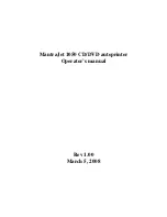
Страница 105: ... 6 13 CHAPTER 6 PAPER DRUM SECTION Gripper shaft unit Gripper collar P0630 P0631 REAR Gripper shaft unit FRONT ...

Страница 106: ...cing base as shown by A on the sketch below The surface indicated by B on the sketch should also align with each other though may need to slide the reinforcing arm a little bit to allow smooth movement of the gripper shaft unit and gripper cover shaft 5 The final position of the gripper shaft will be readjusted if required after running B4 size thin papers or recycled papers If paper wrinkle appea...

Страница 107: ...m timing gear R ass y on the paper drum Use an available 3 mm diameter rod or 2 5 mm Allen wrench to align the elongated hole on the paper drum timing gear R ass y and round hole on the gripper gear to achieve correct positioning P0635 P0634 P0636 P0637 Paper drum timing gear R ass y Gripper gear Gripper gear Paper drum timing gear R ass y Allen wrench 2 5 mm REAR FRONT 8 mm diameter long shaft JI...

Страница 108: ...rum 11 Remove the 8 mm diameter long shaft JIG from the paper drum 12 Close the gripper cover ass y by hand and keep it closed using adhesive tape Make sure to remove the adhesive tape after installing the paper drum in the machine 13 Hook the paper lifter spring and link spring on the paper drum 14 Mount link cover R BB roller flat surface to face outside and paper lifter timing plate ass y on th...

Страница 109: ...haft Precautions on Reassembly Do not make mistake in the direction of the gripper shaft and gripper shaft spring during the assembly Also mount the grippers in correct direction on the gripper shaft and mount the gripper shaft reinforcing arm in correct position Gripper shaft unit P0641 Gripper base Gripper collar Gripper shaft Gripper Gripper Gripper shaft spring P0643 P0642 P0640 ...

Страница 110: ...oving the Paper Lifter 1 Remove gripper shaft unit 2 Remove paper lifter spring 3 Since paper lifter ass y cannot be detached remove only the paper lifter by removing four screws Paper lifter spring P0644 Paper lifter Paper lifter ass y P0645 ...

Страница 111: ...is sequence 3 Run Test mode No 503 Position T sensor 4 Loosen the lock screw M3 x 6 move the position T sensor bracket position up in direction of arrow in photograph and secure at the point at which the buzzer sound changes from long beeps to short beeps 5 Remove the 8 mm diameter long shaft JIG and exit from the Test mode Rear frame plate Paper drum Front frame plate 8 mm diameter long shaft JIG...

Страница 112: ... 6 20 CHAPTER 6 PAPER DRUM SECTION MEMO ...

Страница 113: ...s y 7 6 5 Removing the Paper Ejection Sensor Send 7 6 6 Removing the Paper Ejection Roller Unit 7 7 7 Removing the Paper Ejection Motor 7 7 8 Removing the Paper Ejection Limit Sensor 7 8 9 Removing the Pinch Rollers 7 8 10 Removing the Pinch Slide Ass y 7 9 11 Removing the Pinch Pulse Motors F R 7 10 12 Removing the Pinch HP Sensors F R 7 10 13 Removing the Paper Ejection Sensor Receive 7 11 14 Re...

Страница 114: ...paper ejection unit is in place The paper ejection unit set signal is OFF when not in place The paper ejection sensor checks that the printed paper is ejected properly The paper ejection roller is driven by the paper ejection motor and the rotation of the paper ejection motor is monitored by the paper ejection limit sensor encoder sensor The paper ejection wings can be manually adjusted up or down...

Страница 115: ...on The pinch rollers stay in one set position throughout the printing When the paper size is changed on the paper feed tray the pinch rollers move to the new position when the START key is pressed to continue the printing operation The pinch slide ass y is released or made in contact by the pinch roller release motor The position of the pinch slide ass y is checked by the pinch roller release sens...

Страница 116: ...he receiving tray lock plates on both sides M3 x 6 screw on each side 2 Remove the paper receiving tray from the paper receiving tray support ass y Paper receiving tray support ass y Receiving tray lock plate Paper receiving tray Paper receiving tray support ass y Paper receiving tray P0701 P0702 ...

Страница 117: ... pinch unit from the receiving tray slide rail 3 Removing the Paper Receiving Tray Support Ass y 1 Remove the four mounting screws M4 x 6 and remove the paper receiving tray support ass y from the receiving tray slide rail Paper ejection pinch unit Receiving tray slide rail Receiving tray slide rail Paper receiving tray support Ass y P0703 P0704 ...

Страница 118: ...emoving the Paper Ejection Sensor Send 1 Remove the paper ejection cover ass y 2 Remove the mounting screw M3 x 6 then remove the paper ejection sensor send bracket together with the paper ejection sensor cover 3 Remove the mounting screw M3 x 6 remove the paper ejection sensor cover Remove the paper ejection sensor send Paper ejection cover ass y Paper ejection cover ass y Paper ejection sensor c...

Страница 119: ...ting screws M4 x 8 and remove the paper ejection roller unit 7 Removing the Paper Ejection Motor 1 Remove the paper ejection roller unit 2 Remove the four mounting screws M4 x 8 remove the pinch pulse motor timing belt Remove the paper ejection motor Paper ejection roller unit Paper ejection motor Paper ejection motor Pinch pulse motor timing belt P0708 P0709 P0710 P0711 ...

Страница 120: ...Rollers 1 Remove the paper ejection pinch unit 2 Detach the E ring pull out the pinch roller shaft from the pinch slide plate and remove the spacer and pinch roller Pinch slide plate Paper ejection limit sensor encoder sensor Paper ejection motor P0712 P0713 Pinch roller Spacer P0714 Pinch roller shaft ...

Страница 121: ...M4 x 8 screws 3 Detach the pinch release springs front and rear and disconnect the connectors to the motor and sensor at the front and rear Slide up the pinch slide ass y and remove from the pinch base ass y Pinch cover Pinch release springs Connectors Slide up and remove Pinch slide ass y Pinch base ass y Connectors P0715 P0716 P0717 P0718 ...

Страница 122: ...6 and detach the pinch pulse motor timing belt Remove pinch pulse motors F and R 12 Removing the Pinch HP Sensors F FRONT R REAR 1 Remove the pinch slide ass y 2 From both ends of the pinch slide ass y remove the mounting screw M3 x 6 and remove pinch HP sensors F and R together with their brackets Pinch pulse motor Pinch pulse motor timing belt Pinch HP sensor Pinch HP sensor bracket P0719 P0720 ...

Страница 123: ...1 Remove the paper ejection pinch unit 2 Remove the pinch slide ass y from the pinch base ass y 3 Remove the mounting screw M4 x 8 and disconnect the connector Remove the paper ejection unit safety SW together with the paper ejection unit safety SW attachment spring and bracket 4 Remove the two mounting screws M3 x 14 and remove the paper ejection unit safety SW Connector Paper ejection sensor rec...

Страница 124: ...r release ass y and pinch roller release shaft ass y Make sure that the pinch release detection plate does not strike the pinch roller release sensor 3 Remove the mounting screw M3 x 6 pull out pinch release shaft A and remove the spur gear 4 Remove the pinch roller release motor Two M3 x 6 screws Lower pinch base plate Pinch release detection plate Pinch roller release sensor Pinch release shaft ...

Страница 125: ...CTION SECTION 16 Removing the Pinch Roller Release Sensor 1 Remove the pinch roller release ass y and pinch release shaft ass y 2 Disconnect the connector Remove the pinch roller release sensor Pinch roller release sensor P0728 ...

Страница 126: ...aper ejection unit confirming that the gap between the paper ejection separators and the paper drum is 1 4mm to 2 0mm at the two points indicated by arrows in the photograph 2 If the gap falls outside the specifications remove the adjuster plates on both sides M4 x 8 screws on each side 3 Turn the adjuster screws to adjust the gap between the paper ejection separators and the paper drum 4 Attach t...

Страница 127: ...Pressure Clutch 8 11 6 Removing the Horizontal Pulse Motor Ass y 8 12 7 Removing the Ink Pump Ass y 8 13 8 Removing the Pressure Control Motor 8 14 9 Removing the Ink Sensor PCB 8 16 10 Removing the Clamp Plate Base Ass y 8 18 11 Removing the Inner Pressure Roller Unit 8 19 12 Removing the Engagement Pin 8 31 13 Removing the Position A Sensor No 1 and Position B Lock Confirmation Sensor 8 33 14 Re...

Страница 128: ... for example on the floor the clamp plates for both the 1st and 2nd print drums move to their topmost positions The position B lock confirmation sensor located next to the rear position A sensor and blocked by the position A sensor detection plate confirms that the print drum is at position B for print drum removal When the print drums are reinserted into the machine it is the paper drum position ...

Страница 129: ...pin from the drive joint on the machine to prevent the print drum from being rotated by the machine drive unit With the push of the START key to start printing after the reinsertion of the print drums the drive unit on the machine is moved to the B postion Then the print drums are moved to the horizontal HP sensor position by the drum horizontal motor and then the print drum is engaged with the dr...

Страница 130: ... the drive mechanism drive joint engagement pin flange drive gear flange gear gear Z38 gear Z31 gear Z40 inner pressure drive gear Inner pressure roller vertical movement mechanism The inner pressure roller is lifted up or pushed down during printing by switching the inner pressure clutch ON for 50 ms The inner pressure roller can be pushed down when the 2nd paper feed sensor is ON after the start...

Страница 131: ...ock cam is checked by the lock cam sensor The drum lock sensor confirms that the drum lock lever is in the lock position The drum lock motor rotates in one direction only Lock position Position at which the drum cam sensor changes from OFF to ON Release position Position at which the drum cam sensor changes from ON to OFF 10 Master Clamp Mechanism Refer to Chapter 10 CLAMP UNIT ...

Страница 132: ...efer to the photograph below 4 Remove the front and rear stepped screws Remove the clamp plate base ass y from hanger E on the screen ass y Refer to the photograph on the bottom and on the next page 5 Remove the two mounting screws on the hanger TA M4 x 8 and remove the screen ass y Refer to the photograph on next page E ring and washer to be removed Screen spring P08003 P08004 P08005 Stepped scre...

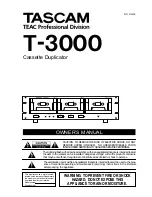
Страница 133: ... 8 7 CHAPTER 8 PRINT DRUM SECTION Hanger E Clamp plate base ass y P08006 P08007 Screen ass y Hanger TA ...

Страница 134: ...nds remove the two mounting screws M4 x 8 and remove the ink volume detection sensor receive ass y When the ink volume detection sensor receive ass y is closed do not apply excessive force in opening it Open it by releasing the hook Print drum cover Ink volume detection sensor receive ass y Connector P08008 P08009 P08010 Hook Hook Snap bands Connector 2 places Connector Screws to remove ...

Страница 135: ...pring 3 Remove the three mounting screws 3 x 8 and remove bottle end cover B 4 Disconnect the connector remove the mounting screw 3 x 8 and remove the ink volume detection sensor receive PCB with the ink volume detection sensor receive attached Bottle end cover spring Ink volume detection sensor receive Connector Layout of components inside the ink volume detection sensor receive ass y P08011 P080...

Страница 136: ...e ass y to the side 3 Loosen the four mounting screws M4 x 6 Remove the dome sheet 4 Disconnect the connector remove the two mounting screws M4 x 8 and remove the ink volume detection sensor send ass y Do not disassemble the ink volume detection sensor send ass y Position B lock plate Flange Dome sheet Connector Ink volume detection sensor send ass y P08015 P08016 P08017 Clamp plate base ass y Fla...

Страница 137: ...rews M4 x 8 and remove the inner pressure clutch Precautions on Reassembly Align the shaft pin with the slot in the clutch shaft Engage the slot in the inner pressure clutch bracket with the protrusion on the bottle guide Inner pressure clutch Shaft pin Protrusion on the bottle guide Slot Inner pressure clutch bracket Slot in the clutch shaft P08018 P08019 P08020 Connector ...

Страница 138: ...ting screws M4 x 6 and remove the dome sheet 3 Disconnect the connector unplug two detachable wire harness bands and remove the horizontal pulse motor ass y by removing two mounting screws M4 x 8 Horizontal pulse motor ass y Connector Detachable wire harness band P08021 P08022 Horizontal pulse motor ass y Horizontal pulse motor ...

Страница 139: ...en the four mounting screws M4 x 6 and remove the dome sheet 4 Remove the inner pressure clutch ass y 5 Slide bottle guide B to one side and disconnect two connectors Remove two mounting screws M4 x 8 to detach the ink pump ass y Connectors Bottle guide B P08023 P08024 Ink pump ass y Slide Bottle guide B a little Ink punp ass y ...

Страница 140: ...emove the dome sheet 5 Lower the inner pressure roller 6 Remove E ring and slide the spur gear aside 7 Pull out parallel pin and remove the metal bearing from the shaft 8 Pull out the connector and remove screw M4x8 to detach the pressure control motor assembly together with the motor mounting bracket P08025 P08026 P08027 Metal bearing E ring Parallel pin Spur gear Spur gear Motor mounting bracket...

Страница 141: ... 8 15 CHAPTER 8 PRINT DRUM SECTION Pressure control motor ass y P08028 P08029 Pressure control motor ass y Connector ...

Страница 142: ...ng screws 3 x 8 and remove bottle end cover B 7 Remove the two mounting screws M4 x 8 and remove the wire harness holding plate 8 Unhook wire harness from the wire harness hook on the bottle guide B and remove bottle guide B 9 Remove bottle guide A Two M4 x 8 screws 7 Disconnect the connector remove the mounting screw M4 x 8 and remove the ink sensor PCB ass y Release lock on the connector of the ...

Страница 143: ...ide A Precautions on Reassembly Engage the protrusions on ink sensor PCB bracket A with the slots in ink sensor PCB bracket B Ink sensor PCB ass y Connector Ink sensor PCB bracket B Ink sensor PCB bracket A Slots in ink sensor PCB bracket B Protrusions on ink sensor PCB bracket A ...

Страница 144: ...APTER 8 PRINT DRUM SECTION Clamp plate base ass y 10 Removing the Clamp Plate Base Ass y 1 Remove the screen ass y 2 Remove the four mounting screws M4 x 8 Remove the clamp plate base ass y P08037 P08038 P08039 ...

Страница 145: ...te base ass y Dome sheet Ink volume detection sensor receive ass y Ink volume detection sensor send ass y Wire holding plate Refer to page 8 16 Inner pressure clutch Bottle guide B Bottle guide A Ink sensor PCB ass y From steps 3 to 7 which continues are all on the front operating side of the machine 3 Disconnect the two connectors detach the wire harness from the two wire saddles and remove the p...

Страница 146: ...en two set screws and remove the spur gear from the inner pressure roller drive shaft 5 Remove two E rings and detach the bearing Spur gear Flange drive gear F E ring 2 pcs P08041 P08042 P08043 P08044 Bearing Inner pressure roller drive shaft ...

Страница 147: ...rming that the inner pressure detection plate is positioned in between the sensor Then remove the two mounting screws M4 x 8 on the print drum flange F ass y and slide the print drum flange F ass y and flange drive gear F to remove E ring on the Flange drive gear P08045 P08047 P08048 P08046 Flange drive gear F Inner pressure detection plate Connector Inner pressure limit sensor encoder sensor Prin...

Страница 148: ...d remove the link plate and link ass y From steps 8 to 15 which continues are all on the rear drive side of the machine 8 Remove C ring and detach print drum rear frame ass y E rings Link plate Link ass y P08049 P08051 P08050 Print drum rear frame ass y C ring ...

Страница 149: ...ECTION 9 Loosen two set screws and remove the spur gear 10 Remove E ring two screws M3x8 and detach one way hinge 11 Remove the bearing One way hinge Spur gear P08052 P08053 P08054 P08055 Bearing Inner pressure roller drive shaft ...

Страница 150: ...plug two sensor connectors and remove one detachable wire harness band 13 Remove two mounting screws M4 x 8 on the print drum flange R ass y and slide the print drum flange R ass y together with flange drive gear shaft attached to remove P08056 P08057 P08058 Print drum flange R ass y Flange drive gear shaft ...

Страница 151: ... 8 25 CHAPTER 8 PRINT DRUM SECTION E rings 14 Detach the E rings and remove the link plate and link ass y Link plate Link ass y P08059 ...

Страница 152: ...etal bearing 15 Detach ink shaft drive plate by removing screw M4x8 and remove metal bearing with flange spur gear and then pull out the ink drive shaft Do not misplace the metal bearing between the spur gear and the O ring Metal bearing O ring Ink drive collar Ink drive shaft P08060 P08061 P08062 P08063 P08064 ...

Страница 153: ...pin C on the inner pressure roller unit from the slot in the inner pressure roller support plate and remove the inner pressure roller unit Refer to page No 8 28 for the assembly instructions P08065 P08066 P08067 Pin C REAR Inner pressure roller spring Inner pressure roller support plate Mounting screw Pin C Inner pressure roller support plate Mounting screw Inner pressure roller spring ...

Страница 154: ... unit Fix the inner pressure roller unit on the print drum by two mounting screws after attaching pin C in the slot in the inner pressure roller support plate and after attaching the inner pressure roller springs Slot in the Inner pressure roller support plate Pin C Inner pressure roller spring P08068 P08069 P08070 ...

Страница 155: ...able wire harness band and plug two connectors 6 Mount print drum flange F ass y while placing flange drive gear F on flange drive gear shaft The two set screws on the flange drive gear F should face in the easy to access direction after the 8 mm diameter shaft JIG is inserted in next step 7 Tighten set screws by step 8 7 Align the position of print drum flanges R and F by inserting 8 mm diameter ...

Страница 156: ...long shaft JIG 12 Mount print drum rear frame ass y and attach C ring 13 Attach connector to the inner pressure limit sensor encoder sensor 14 Mount print drum front frame ass y run wire harness though two wire harness saddles and connect two connectors on the print drum PCB 15 Install following remaining parts on the print drum to complete the assembly Ink sensor PCB ass y Bottle guide A Make sur...

Страница 157: ...e print drum Print drum cover Screen ass y Print drum rear frame ass y 2 Remove two mounting screws of the flange drive gear R Cap screw M4x8 4 mm spring washer 3 Remove the engagement pin by loosening two set screws P08076 P08075 Engagement pin Flange drive gear shaft Flange drive gear R Cap screws ...

Страница 158: ...ngagement pin to align the angle of the engagement pin then tighten the two set screws on the engagement pin while pushing it against the flange drive gear shaft 4 Mount flange drive gear R using two cap screws 5 Remove 8 mm diameter long shaft JIG and drum joint alignment lock JIG 6 Mount following parts to complete the assembly Print drum rear frame ass y Screen ass y Print drum cover Slit on ba...

Страница 159: ...move mounting screw M4x8 from position A sensor mounting bracket R Unplug connectors from both the position A sensor No 1 and position B lock confirmation sensor to free both sensors with the mounting bracket attached Position A sensor mounting bracket R Position B lock confirmation sensor Position A sensor No 1 P08081 ...

Страница 160: ...reen ass y Dome sheet 2 Rotate the gear on the pressure motor ass y by hand until the sensor actuator plate slides out of the sensor in the direction shown on the photograph below 3 Unplug the connector and remove the pressure HP sensor Sensor actuator plate Gear on the pressure control motor ass y Pressure HP sensor P08082 P08083 slide ...

Страница 161: ...emove following parts from the print drum Side frames L and R Screen ass y Dome sheet Ink volume detection sensor send ass y 2 Unplug connector remove mounting screw M4x8 and remove the inner pressure detection sensor with mounting bracket Connector P08084 Inner pressure detection sensor ...

Страница 162: ... other Removing the Drive transmit release sensor and Horizontal centering HP sensor 3 Unplug the connectors and remove the two sensors Removing the Position A sensor No 2 3 Remove the mounting screw M4x8 and unplug connector Remove the sensor attached on the mounting plate The surface of the MF holder and Support shaft should be about flat with each other Drive transmit release sensor P08085 P080...

Страница 163: ...and remove E ring from flange drive gear ass y 3 Remove three mounting screws M4x12 and remove flange drive gear stay F 4 Remove E ring and detach sensor actuator plate 5 Remove the pressure limit sensor Flange drive gear stay F Flange gear Sensor actuator plate Precautions for Reassembly Insert 8 mm diameter long shaft JIG through the holes in the print drum flange ass y F and R to align the two ...

Страница 164: ...m Locking Unit 1 Disconnect the two connectors remove the three mounting screws M4 x 8 and remove the print drum locking unit Print drum lock position sensor P08090 P08091 P08092 Print drum No 2 Print drum No 1 Print drum locking motor Print drum lock cam sensor ...

Страница 165: ...r 1 For both 1st print drum set sensor and 2nd print set sensor remove mounting screw M4x8 to detach the sensor with the mounting bracket attached 1st print drum set sensor P08093 P08094 P08095 2nd print drum set sensor Print drum set sensor with mounting bracket attached ...

Страница 166: ...uires adjustment loosen the two lock screws refer to photograph on next page and turn the gap adjustment knob to adjust Rotating upward reduces the gap while rotating downward increases the gap 7 After adjusting firmly retighten the two lock screws 8 Run an actual print test Test chart No 11 print speed 3 print density 1 A3 size standard printing paper to check the density balance Precautions on A...

Страница 167: ...P08097 Too little Too much Correct Hole on the plastic flange gear Screw Engagement pin Inner pressure roller gap adjustment start position P08098 S08099 The hole on the flange gear and the screw is at same position and the engagement pin is in vertical position Lock screw Lock screw P08100 Print drum as seen looked up at angle from the bottom ...

Страница 168: ... Adjustment Procedure 1 Make master using Test Mode No 51 2 Feed 1 000 sheets of standard A3 size white printing paper at print speed No 5 print density at No 3 and print position at center and check that the master on the print drum elongation is 0 to 0 5 mm for both the 1st and 2nd print drums 3 If the elongation is not within the specifications adjust the Teflon tape thickness around the print ...

Страница 169: ...aster has shifted to the front move drum positioning block R to the right If it has shifted to the rear move drum positioning block R to the left The adjustment amounts for drum positioning block R are shown below depending on the amount of master shift If the master has shifted 0 5 mm move the drum positioning block R horizontally 0 1 mm If the master has shifted 1 0 mm move the drum positioning ...

Страница 170: ... 8 44 CHAPTER 8 PRINT DRUM SECTION MEMO ...

Страница 171: ... 9 2 1 Vertical Print Position Mechanism 9 2 Disassembly 9 4 1 Removing the Print Drum Drive Unit same for 1st and 2nd 9 4 2 Removing the Print Positioning Pulse Motor 9 6 Adjustment 9 7 1 Adjusting the Datum Print Position Phase Between Print Drum and Paper Drum 9 7 ...

Страница 172: ...direction to bring the image down If the vertical print position key is pressed while the machine is in idle the panel display changes but the motor still does not rotate The actual print position does not change until the START button is pressed for the print operation If 0 is selected by test mode No 091 the print position changes only at the start of the printing If 1 is selected by test mode N...

Страница 173: ...ION Print drum drive unit P0913 View with the Print drum drive cover removed P0914 Print positioning pulse motor Vertical centering sensor Print positioning pulse motor Planetary gear mechanism inside Print drum drive cover Print drum drive unit ...

Страница 174: ...um drive unit P0901 P0902 P0903 Disassembly 1 Removing the Print Drum Drive Unit same for 1st and 2nd print drum Refer to next page for PRECAUTIONS before disassembly 1 Remove the main cover ass y 2 Disconnect the two connectors remove the fourmounting screws M4 x 8 and remove the print drum drive unit ...

Страница 175: ...he paper drum at 180 degrees flat surface facing down Then insert another piece of 8 mm dia x 160 mm shaft JIG into the phase alignment hole on the 1st print drum drive unit marked 1 for the 1st print drum drive unit Attach the 1st print drum drive unit while matching the positioning marks on the gears Then do the same for the 2nd print drum drive unit using the alignment hole marked 2 8 mm dia x ...

Страница 176: ...910 P0911 2 Removing the Print Positioning Pulse Motor 1 Remove the print drum drive unit 2 Remove the vertical centering sensor together with the sensor bracket M3 x 6 screw 3 Remove the assist plate M4 x 8 screw 4 Remove the print drum drive cover Six M4 x 8 screws 5 Detach the E ring and remove the spur gear 6 Remove the four mounting screws M3 x 6 then remove the print positioning pulse motor ...

Страница 177: ...p plate 6 Run prints print speed 3 print position center and check that the line s is printed 10 mm 1 mm from the leading edge of the print paper 7 If the line s is not printed within the given distance from the leading edge of the paper rum test mode No 681 vertical center position adjustment on the print drum for the print drum s on which the line was not printed within the given distance Increa...

Страница 178: ... 9 8 CHAPTER 9 VERTICAL PRINT POSITION SECTION MEMO ...

Страница 179: ...osition 10 5 4 Clamp Unit Initial Position 10 5 5 Angular Sensors 10 5 6 Clamp Plate Movement 10 6 Disassembly 10 7 1 Removing the Clamp Unit Same for 1st and 2nd 10 7 2 Removing the Angular Sensor PCB 10 7 3 Removing the Clamp Slide HP Sensor and Clamp Slide Sensor 10 8 4 Removing the Clamp Plate HP Sensor and Clamp Plate Loading Position Sensor 10 8 ...

Страница 180: ...rth motion is driven by the clamp slide motor The position of the clamp is checked by the clamp slide HP sensor and clamp slide return sensor The opening and closing action is driven by the clamp opening and closing motor and the position for the clamp opening and closing is checked by the clamp plate HP sensor clamp plate loading position sensor and angular sensor P1001 1st Clamp unit for print d...

Страница 181: ...NIT P1002 Clamp Unit TOP VIEW P1003 Clamp Unit REAR VIEW Clamp Unit FRONT VIEW P1004 Clamp slide motor Clamp slide motor Clamp opening and closing motor Clamp engaging shaft Clamp opening and closing motor Clamp engaging shaft ...

Страница 182: ...the main motor the print drum rotates at 30 rpm and stops when position A sensor detection changes from OFF to ON 2 Main clutch is engaged to rotate the print drum in the forward direction by the maim pulse motor 3 The main pulse motor stops 800 msec after position A sensor detection changes from ON to OFF 4 300 msec later the main pulse motor rotates the print drum in reverse direction 5 Main pul...

Страница 183: ...ning 1 Clamp opening and closing motor rotates the clamp engaging shaft in the counterclockwise direction looking from the rear 2 Clamp opening and closing motor stops when clamp plate HP sensor detection changes from OFF to ON 3 300 msec later the clamp opening and closing motor rotates in the opposite direction until the clamp plate HP sensor detection changes from ON to OFF 5 Angular Sensors Th...

Страница 184: ...ed by test mode No 391 master top release repetition If 1 through 5 is selected by test mode No 391 above 4 and 5 will be repeated for the set repetition by test mode No 391 and goes to next step 6 6 The clamp unit goes through initial positioning movement Top clamp plate closing movement 1 Clamp unit makes initial positioning movement 2 Clamp slide motor activates to engage clamp engaging shaft o...

Страница 185: ...screws M4 x 8 and remove the clamp unit P1005 2 Removing the Angular Sensor PCB 1 Remove the two mounting screws M3 x 5 and remove the angular sensor cover 2 Unplug connector and remove the angular sensor PCB 1st Clamp unit for print drum No 1 2nd Clamp unit for print drum No 2 P1006 P1007 Angular sensor cover Connector Angular sensor PCB 180 Angular sensor 0 Angular sensor Angular safety sensor P...

Страница 186: ... with mounting bracket P1009 Clamp slide sensor Clamp slide HP sensor 4 Removing the Clamp Plate HP Sensor and Clamp Plate Loading Position Sensor 1 Remove the mounting screw M3 x 6 then remove both the clamp plate HP sensor and clamp plate loading position sensor together with mounting bracket P1010 Clamp plate HP sensor Clamp plate loading position sensor CLAMPUNIT Top View CLAMPUNIT Rear View ...

Страница 187: ... 11 6 6 Removing the Master Disposal Motor 11 7 7 Removing the Disposal Plate Limit Sensor and Disposal Plate HP Sensor 11 8 8 Removing the Master Disposal Jam Sensor 11 8 9 Removing the Disposal Plate Motor 11 9 10 Removing the Vertical Transport Roller G and Master Disposal Belt 1st Master Disposal Unit 11 10 11 Removing Vertical Transport Roller J 1st Master Disposal Unit 11 11 12 Removing the ...

Страница 188: ...hen the master disposal count reaches 50 or if an overcurrent is detected during compression plate compression operation The disposal box safety SW checks that the master disposal box is in position The disposal box empty detection sensor checks that any masters remain inside the master disposal box after masters have been discarded To reset the disposal box full indication detach the master dispo...

Страница 189: ... reached 4 The print drum stops when the print drum has rotated to the next master tail clamp position A The master disposal jam sensor checks that the master has been correctly disposed of when the master disposal motor has stopped The master disposal motor limit sensor encoder sensor monitors the speed of the master disposal motor 5 Disposal Compress Action The disposal compress action is perfor...

Страница 190: ...he rear first Detach the wire harness from the wire harness clamp with the rear end of the unit pulled out slightly Precautions for Reassembly Insert the flat section of the master disposal unit frame plate into the gap between the master disposal stay and the master disposal unit guide REAR FRONT Master disposal box Master disposal unit Master disposal unit guide Master disposal stay Flat section...

Страница 191: ...ter disposal unit Front sensor 3 pins send Rear sensor 4 pins receive 2nd master disposal unit Front sensor 4 pins receive Rear sensor 3 pins send 3 Removing the Master Tail Clamp Fan 1st Master Disposal Unit Only 1 Disconnect the connector remove the two mounting screws M3 x 20 on each fan and remove the fan Disposal box empty detection sensor receive Disposal box empty detection sensor send One ...

Страница 192: ...he Master Compression Limit Sensor Encoder Sensor and Master Compression HP Sensor The procedure is common for both the 1st and 2nd master removal unit 1 Remove the mounting screw M4 x 6 lift up the master compression sensor ass y disconnect the connector and remove the master compression limit sensor and master compression HP sensor Master disposal motor limit sensor Master disposal motor limit s...

Страница 193: ...nnector on the master disposal motor cut the wire harness band remove the three mounting screws M4 x 6 and remove the master disposal motor cover 4 Remove the master disposal motor ass y Three M4 x 6 screws 5 Remove the three mounting screws M3 x 5 then remove the master disposal motor Master compression sensor ass y Master disposal limit sensor ass y Connector Wire harness band Master disposal mo...

Страница 194: ...posal Jam Sensor The procedure is common for both the 1st and 2nd master removal unit 1 Remove the vertical transport roller holder ass y Two M4 x 6 screws 2 Disconnect the connector remove the mounting screw M3 x 6 and remove the master disposal jam sensor together with the bracket Master disposal jam sensor Vertical transport roller holder ass y Disposal plate limit sensor Disposal plate HP sens...

Страница 195: ... the 1st and 2nd master removal unit 1 Cut the wire harness band disconnect the connector remove the two mounting screws M4 x 6 and remove the disposal plate motor ass y 2 Remove the disposal plate motor Two M2 6 x 5 screws Disposal plate motor ass y Disposal plate motor ass y P1117 P1118 Disposal plate motor ...

Страница 196: ...out the roller and remove 5 Loosen the set screw on gear Z24 and remove from vertical transport roller G The gear on the Gear Z24 should face inside and the boss with the set screw faces outside 6 Pull out and remove vertical transport roller G from the keyhole shaped hole in the frame plate 7 Remove the master disposal belt from vertical transport roller G Vertical transport roller G Guiding roll...

Страница 197: ...crew 5 Loosen the set screw on the rear gear Z21 and remove from vertical transport roller J 6 Remove the four mounting screws M4 x 6 on the master disposal guide lower ass y and slide the ass y back a little 7 Detach the E rings and metals on both sides and remove vertical transport roller J Refer to page 11 19 for removing these parts from the 2nd Master Disposal Unit Vertical transport roller J...

Страница 198: ...y 2 Remove the master disposal jam sensor ass y 3 Remove the disposal plate motor ass y 4 Move the disposal plate to an accessible position remove the three mounting screws M3 x 6 and remove the disposal plate Precautions for Reassembly Align the direction of the disposal plate with the disposal plate detection plate Avoid bending the disposal plate shaft Disposal plate P1126 P1125 ...

Страница 199: ...sor ass y 3 Detach the E ring and remove the intermediate gear 4 Detach the E ring and remove the spur gear 5 Detach the E ring and metal Then slide and remove the disposal plate shaft in the direction in which the disposal plate detection plate is attached and remove Intermediate gear Spur gear Disposal plate shaft Disposal plate detection plate Disposal plate sensor ass y Disposal plate shaft P1...

Страница 200: ...late M4 x 6 screw 2 Disconnect the connector remove the four mounting screws M4 x 6 and remove the master compression motor together with the master compression motor bracket 3 Remove the two mounting screws M3 x 6 then remove the master compression motor from the master compression motor bracket Motor support plate Master compression motor Master compression motor bracket P1129 ...

Страница 201: ...move the disposal plate sensor ass y 3 Remove the compression gear support plate ass y Four M4 x 6 screws 4 Remove the mounting screws one M4 x 10 screw on each side and compression plate fulcrum from both sides then remove the master compression plate Precautions for Reassembly Refer to next page Compression gear support plate ass y Master tail clamp fan ass y Compression plate fulcrum Compressio...

Страница 202: ...STER DISPOSAL SECTION Precautions for Reassembly Insert the Metal on the Master compression gear C in the elongated hole of the Master compression Plate Master compression gear C Metal Master compression plate P1134 P1135 ...

Страница 203: ...over Two M3 x 6 screws 2 Remove the mounting screw M3 x 6 and safety SW fulcrum shaft then remove the safety SW ass y 3 Disconnect the connectors remove the two mounting screws M3 x 14 and remove the disposal box safety SW from the safety SW bracket Safety SW cover Safety SW ass y Safety SW fulcrum shaft Disposal box safety SW Safety SW bracket Connectors P1136 P1137 P1138 ...

Страница 204: ...he two connectors and remove the two mounting screws M4 x 8 Since the master disposal unit protrudes from the rear pull out and remove from the front first Precautions for Reassembly Insert the flat section of the master disposal unit frame plate into the gap between the master disposal stay and the master disposal unit guide FRONT Master disposal box Master disposal unit REAR P1139 ...

Страница 205: ... lower II ass y and move to one side 9 Remove the E rings and metals on both sides and remove vertical transport roller G 10 Remove the E ring and bearing on one side of the guiding roller slide the roller and remove the master disposal belt 19 Removing Vertical Transport Roller J 2nd Master Disposal Unit 1 Remove the vertical roller holder 2 Remove the master disposal jam sensor ass y 3 Loosen th...

Страница 206: ... 11 20 CHAPTER 11 MASTER DISPOSAL SECTION MEMO ...

Страница 207: ... FB Original Scanning Movement Book Mode OFF 12 7 5 Book Mode Pre Scan Mechanism 12 7 6 Book Mode Scanning Mechanism 12 7 Disassembly 12 8 1 Removing the Scanner Unit 12 8 2 Removing the Stage Glass 12 9 3 Removing the Lamp 12 10 Adjustment 12 11 1 FB Read Pulse Motor Speed Adjustment 12 11 2 FB Scan Start Position Adjustment 12 11 3 FB Horizontal Scan Position Adjustment 12 12 ...

Страница 208: ...r table is in position The flat bed set switch also acts as an interlock SW When the scanner table is opened the switch cuts power to the main motor clamp motor master loading fan print positioning pulse motor master compression motor disposal plate motor paper ejection motor pinch pulse motor master making unit shifting motor and TPH power supply Scanner table slide lever Scanner table Flat bed s...

Страница 209: ... 12 3 CHAPTER 12 FB ORIGINAL SCANNING SECTION MEMO ...

Страница 210: ...r carriage and lamp carriage are able to move horizontally along the rails attached to the respective sliders The mirror carriage carries two mirrors mirror 2 and mirror 3 and the lamp carriage carries the original illumination lamp and lamp inverter and mirror 1 The mechanism uses a full half rate mirror scanning system in which the mirror carriage moves 1 2 L mm as the lamp carriage moves L mm i...

Страница 211: ...em diagram Lamp carriage Fixed pulley 2 FB read pulse motor Sliding pulley 2 Sliding pulley 1 Fixed pulley 1 Mirror carriage Wire Spring Original illumination lamp Wire spool pulleys CCD Lens Lens ass y Reflector S1206 Mirror 2 Mirror 3 Mirror 1 Mirror carriage S1205 Lamp carriage ...

Страница 212: ...riage to the left in the photograph Once the FB AF HP sensor turns ON blocked it is moved a further set distance before the operation ends this is the standby position The detection plate on the FB AF HP sensor is attached to the lamp carriage No movement is made if the FB AF HP sensor is ON from the start The flatbed is moved to the shading position after moving to the standby position Then the l...

Страница 213: ...ated and the lamp carriage starts to move in the scanning direction Once shading compensation has been performed and the lamp carriage has moved the specified distance the FB read pulse motor stops and the lamp turns off The lamp carriage is then returned to the standby position to complete the pre scan operation Book mode scanning is performed next 6 Book Mode Scanning Mechanism Once the pre scan...

Страница 214: ...or and raise and remove the scanner unit The scanner unit is heavy precision component Handle with care Precautions for Reassembly After reinstalling slide the scanner table and remove the scanner unit securing screw on the mirror carriage Reset the error status using Test mode No 155 Scanner Release Action In replacing the scanner unit memo down the three test mode setting numbers printed on a st...

Страница 215: ...er table cover Scanner cover right Scanner cover rear Scanner cover left Scanner cover front 2 Remove the two special stepped screws and remove the original stopper The original stopper is engaged from underneath Move it toward the paper feed side before removing it upward 3 Remove the stage glass P1209 Original stopper Stage glass ...

Страница 216: ...ove the top L stay by removing four screws M3 x 6 4 Bring the lamp carriage to the large cutaway section on the scanner frame from which the top L stay was removed 5 Remove the two screws M3 x 6 detach the wire harness from the wire clamp and wire saddle and then remove the lamp P1210 P1211 Scanner frame Lamp Lamp carriage Top L stay Scanner frame ...

Страница 217: ...st them using test mode No 182 FB scanning speed adjustment Prior to this adjustment first adjust the image elongation and shrinkage in master making area refer to page 14 23 2 FB Scan Start Position Adjustment Checks and procedure 1 Place A3 size papers on the paper feed tray place test chart No 11 on the stage glass and make one to one size image master and make prints 2 Looking at the print con...

Страница 218: ...tray place test chart No 14 on the stage glass and make one to one size image master and make prints 2 Inspect the master made on the print drum and confirm that the pattern from the original is not missing on the left or right of the master on the print drum 3 If the pattern is missing adjust using test mode No 180 FB horizontal scan position adjust ...

Страница 219: ... y 13 6 2 Removing the Original Pickup Roller 13 8 3 Removing the Original Stripper Roller 13 9 4 Removing the Original IN Sensor 13 10 5 Removing the AF Read Pulse Motor 13 11 6 Removing Other Rollers 13 12 Adjustment 13 19 1 AF Scanning Start Position Adjustment 13 19 2 AF Horizontal Scanning Position Adjustment 13 19 3 AF Read Pulse Motor Speed Adjustment Image Elongation and Shrinkage Adjustme...

Страница 220: ...AF original registration sensor the AF read pulse motor operates in the forward direction This raises the original pickup roller while rotating the original registration roller the two original read rollers 1 2 and the original ejection roller all of which are linked by the timing belt in the feed direction The original stops briefly after it has been moved 90 mm from the original set position The...

Страница 221: ...ginal registration sensor Original stripper pad Original stripper roller Original stopper Original pickup roller Original detection sensor P1303 Original guide fence Original stopper Original registration roller Original read roller 1 Original ejection roller AF white roller Original registration sensor Original stripper roller Original detection sensor Original pickup roller ...

Страница 222: ...d as soon as scanning is complete Once the original is transported a preset distance after the original OUT sensor deactivates the AF read pulse motor stops the lamp carriage is returned to the standby position and the AF original scanning operation is complete The auto base control function does not operate in the Photo Duo or Dot process modes 3 AF Original Scanning Mechanism Upon completion of ...

Страница 223: ... 13 5 CHAPTER 13 AF SCANNING SECTION Original registration roller P1305 AF read pulse motor Original OUT sensor Original ejection roller Original IN sensor AF white roller Original read roller 1 ...

Страница 224: ... M4 x 6 at the front of the AF cover remove the two screws M4 x 10 from underneath and then remove the AF cover 2 Unplug the two sensor connectors detach the detachable wire harness band and then remove the sensor bracket ass y by removing two screws M3 x 4 P1306 AF cover P1307 Detachable wire harness band Sensor bracket ass y ...

Страница 225: ...n remove the original pick up roller ass y towards the front by sliding the rear drive gear of the original pickup roller out through from the hole on the AF frame plate P1308 Metal bushing P1309 P1310 P1311 Metal bushing Platic lock ring Platic lock ring Original pickup roller ass y Hole on the AF frame Original pickup roller ass y FRONT REAR ...

Страница 226: ...roller ass y Refer to previous two pages 2 Detach the lock ring open the end of the K holder and then remove the pickup roller Take care not to lose the K holder C and Parallel pin as they come apart P1312 K holder Lock ring Pickup roller K holder K holder C Parallel pin Original pickup roller ass y P1313 ...

Страница 227: ...low 4 Remove the E ring and slide the K holder F frame in the direction of the arrow mark Then remove the parallel pin from the shaft and remove the K holder F frame 4 Remove the original stripper roller Precautions on Reassembly When engaging the parallel pin with the K holder F frame insert it into the shallower groove on the K holder F frame Note the direction of the original stripper roller It...

Страница 228: ... the AF cover remove the two screws M4 x 10 from underneath and then remove the AF cover 2 Remove one screw M3 x 8 and disconnect the connector to remove the original IN sensor Precaution on Reassembly After placing a new original IN sensor adjust the sensor sensitivity by using test mode No 752 P1316 Original IN sensor ...

Страница 229: ...F cover 2 Remove one screw M4 x 6 from the wire harness bracket ass y and set the bracket ass y aside 3 Remove the open lever with the open lever spring attached 4 Remove the tension spring and by removing two screws M3 x 6 detach AF read pulse motor from the AF unit together with the motor tension bracket AF read pulse motor Open lever P1317 P1318 P1319 Open lever spring Motor tension bracket Ten...

Страница 230: ...ont of the AF cover remove the two screws M4 x 10 from underneath and then remove the AF cover 3 Unplug the connector and remove two screws M3 x 6 to detach AF control PCB 4 Cut loose one wire harness band indicated by an arrow mark on the photograph and remove seven screws M4 x 10 and 2 screws M4 x10 washer to detach the AF drive unit AF control PCB P1320 P1321 AF Drive unit ...

Страница 231: ...d 10 Remove four screws M4 x 6 and remove the motor bracket ass y 11 Loosen the screw on the idler ass y and remove the idler spring 12 Remove white plastic clip and remove the spur gear and then remove E ring to detach the gear ass y located under the spur gear The timing belt 1 comes off Precaution on Reassembly The gear ass y contains one way clutch The surface with the boss should face outward...

Страница 232: ... 13 14 CHAPTER 13 AF SCANNING SECTION Layout of the Rollers AF white roller P1324 FRONT REAR Original read roller 1 Original read roller 1 Original ejection roller Original registration roller ...

Страница 233: ...l bushing 15 Remove plastic lock ring from the front of the original registration roller shaft and remove metal bushing 16 Detach the original registration roller P1325 P1326 P1327 Timing pulley Original registration roller Original registration roller Plastic lock ring FRONT REAR Timing pulley Parallel pin Original registration roller Plastic lock ring E ring Metal bushing Metal bushing FRONT REA...

Страница 234: ...riginal read roller 1 shaft and remove the dial together with parallel pin 16 Remove timing pulley ass y and E ring Then remove metal bushing 17 Detach the original read roller 1 Precaution on Reassembly The timing pulley ass y contains one way clutch Make sure to install it back in the correct direction P1328 Timing pulley P1329 P1330 Original read roller 1 Dial Plastic lock ring Original read ro...

Страница 235: ...tach the metal bushing 15 Remove plastic lock ring from front of the original read roller 2 shaft and detach the metal bushing 16 Detach the original read roller 2 Original read roller 2 P1331 P1332 P1333 Plastic lock ring Timing pulley Parallel pin E ring Metal bushing Metal bushing Timing pulley Original read roller 2 Plastic lock ring Original read roller 2 Plastic lock ring FRONT REAR FRONT RE...

Страница 236: ...he metal bushing 15 Remove plastic lock ring from front of the original ejection roller shaft and detach the metal bushing 16 Detach the original ejection roller shaft Original ejection roller Plastic lock ring Timing pulley Parallel pin E ring Metal bushing Metal bushing FRONT REAR P1334 Timing pulley Original ejection roller Plastic lock ring REAR Original ejection roller Plastic lock ring FRONT...

Страница 237: ...e prints 2 Examine the master created on the print drum and confirm that the e images on the left and right of the original is not missing 3 If the e images are not made on the master make adjustment using test mode No 782 AF Horizontal Scan Position Adjustment Test chart No 14 3 AF Read Pulse Motor Speed Adjustment Image Elongation and Shrinkage Adjustment Checks and adjustment procedure 1 Place ...

Страница 238: ...CTION 4 AF Original IN Sensor Sensitivity Adjustment Adjustment procedure 1 With no original on the AF unit activating test mode No 752 original IN sensor sensitivity adjustment will automatically adjusts the sensitivity of the sensor ...

Страница 239: ...H Ass y 14 8 7 Removing the Thermal Pressure Motor Ass y 14 9 8 Removing the Master Making Unit 14 10 9 Removing the Write Roller 14 14 10 Removing the Master Loading Roller Ass y 14 16 11 Removing the Master Positioning Sensor 14 17 12 Removing the Master Loading Motor 14 18 13 Removing the Master Disposal Fan and Write Roller Temperature Sensor 14 19 14 Removing the Cutter Unit 14 20 Adjustment ...

Страница 240: ...tion 3 TPH Elevation Mechanism The TPH is moved up and down by the thermal pressure motor and the position is checked by the thermal pressure sensor The TPH is initially at the TPH pressure release position TPH pressure release position The position at which the thermal pressure sensor goes off when the motor is rotated in the release direction TPH pressure applied position The position at which t...

Страница 241: ...ting starts when the print drum is at the 298 8 position The print drum rotates during master cutting The switch is depressed after the cutter motor starts rotating and the motor stops again when the switch is no longer depressed Initialization Movement The cutter is initialized when the power is switched on during All Reset and when master making begins Initialization is not performed if the cutt...

Страница 242: ...l 3 Remove the volume detection sensor receive bracket and volume detection sensor send bracket One M3 x 6 screw each 4 Remove the mounting screw M3 x 6 on the master volume detection sensors receive and send disconnect the connectors and remove the sensors Scanner table Master making unit Master roll Volume detection sensor receive bracket Volume detection sensor send bracket P1401 P1402 ...

Страница 243: ...ving the Tension Roller 1 Open the master making unit and remove the master roll 2 Detach the E ring from one side and remove the tension roller Master volume detection sensor receive Master volume detection sensor send Tension roller P1403 P1404 ...

Страница 244: ...he two mounting screws M3 x 6 on the master guide ass y to free the ass y 3 Remove the two mounting screws M3 x 6 on the underside of the master guide ass y disconnect the connector and remove the master detection sensor Front unit cover Rear unit cover Master guide ass y Connector Master detection sensor P1405 P1406 P1407 P1408 ...

Страница 245: ...ter end sensor connector and remove the master making unit lower cover ass y Precautions for Reassembly Insert the bosses on both sides of the master making unit into the slots on the sides of the master making unit lower cover ass y Master making unit lower cover ass y Boss on side of master making unit Slot on end of master making unit lower cover ass y P1409 P1410 P1411 ...

Страница 246: ...he TPH Ass y 1 Remove the master making unit lower cover ass y 2 Detach the ground wire M3 x 6 screw 3 Remove the two mounting screws M3 x 6 disconnect the two connectors and remove the TPH ass y Precautions for Reassembly 1 Align the half pierced section with the hole in the TPH ass y shaft 2 If the TPH is replaced enter the new TPH registance value using Test Mode No 288 Master end sensor cover ...

Страница 247: ...ss y 1 Remove the master making unit lower cover ass y 2 Remove the TPH ass y 3 Remove the springs on both sides 4 Disconnect the connector remove the four mounting screws M3 x 6 and remove the thermal pressure motor ass y Spring Connector Thermal pressure motor ass y P1416 P1417 ...

Страница 248: ... unit cover Unit cover F Unit cover R 2 Open the scanner table 3 Remove the FB safety SW ass y Three M4 x 8 screws 4 Remove the FB lock plate F Two M4 x 8 screws 5 Remove the wire box cover Three M4 x 8 screws and one M4 x 8 screw 6 Remove the wire blind plate Two M3 x 6 screws FB lock plate F FB safety SW ass y Wire box cover Wire blind plate P1418 P1419 P1420 P1421 ...

Страница 249: ...TION 7 Remove the PCB cover M3 x 6 screw 8 Disconnect the three connectors remove the mounting screw M3 x 6 and then pull the wire holder out of the frame plate together with the bracket PCB cover Connectors Wire holder P1422 P1423 P1424 ...

Страница 250: ...er making unit and remove position sensor bracket 2 M4 x 8 screw 11 Move the master making unit toward the master holder until a hand can be inserted Lift up the master holder side slightly and move toward the paper ejection side to allow removal of the spur gear on the master making unit shaft Now remove the master making unit Position sensor bracket 2 FRONT REAR P1425 P1426 P1427 ...

Страница 251: ... long shaft positioning shaft 4 With the jigs still in place align the master making unit shaft spur gear with the end face of the master making unit shaft and side of the spur gear on both sides and then secure with the two set screws on each Secure the master making unit shaft spur gears after aligning the front and rear to have matching amounts and directions of backlash 5 Remove the jigs 6 Run...

Страница 252: ...g the mounting screw of the pulley Photograph below 5 Remove the write roller plate M4 x 8 screw 6 Detach the bearing and remove the write roller Precautions for Reassembly Align the flat cut face on the write roller shaft against the flat cut face on the pulley hole In replacing the write roller input the diameter data of the new write roller data comes with each new write roller with test mode N...

Страница 253: ... 14 15 CHAPTER 14 MASTER MAKING SECTION Tensioner Timing belt Pulley Write roller shaft REAR Write roller shaft Bearing Write roller plate P1434 P1435 ...

Страница 254: ...er making unit 2 Detach the E ring and remove intermediate gear 3 Disconnect the master positioning sensor connector remove the two mounting screws M3 x 6 on either side and remove the master loading roller ass y Connector of master positioning sensor P1436 P1437 Master Making Unit REAR VIEW FRONT REAR ...

Страница 255: ...ding roller ass y Master loading roller ass y Intermediate gear Master loading roller Master positioning sensor Master Loading Roller Ass y 11 Removing the Master Positioning Sensor 1 Remove the master making unit 2 Remove the master loading roller ass y 3 Remove mounting screw M3 x 6 and dismount the master positioning sensor ...

Страница 256: ... 12 Removing the Master Loading Motor 1 Remove the master making unit 2 Disconnect the connector and remove the master loading motor with the motor bracket attached Two M3 x 6 screws P1441 Connector Master loading motor with mounting bracket ...

Страница 257: ...ter detection sensor connector and remove the master guide ass y Two M3 x 6 screws 4 Disconnect total of four master disposal fan connectors remove the two mounting screws M3 x 20 and remove the master disposal fan 5 Disconnect the connector remove the two mounting screws M3 x 6 and remove the temperature sensor Master disposal fan 4 pieces Write roller temperature sensor P1442 P1443 P1444 ...

Страница 258: ... ass y 3 Remove the master making unit sensor cover 4 Remove the cutter guide 5 Disconnect the cutter unit connector remove the mounting screw M4 x 8 and remove the cutter unit Precautions for Reassembly After installation activate Test Mode No 250 cutter motor cycle action to confirm the cutter movement Cutter unit P1445 P1446 P1447 ...

Страница 259: ...ncorrectly adjusted the master may start slipping out of the clamp plate or master skewing on the print drum may occur during the printing Master removal error may also occur 2 Master Tail Clamp Range Adjustment Checking and Adjustment Procedure 1 Make marking on the clamped master at the tip end of the closed tail clamp plate 2 Measure the distance from the mark to the top of the master confirmin...

Страница 260: ...p Checking and Adjustment Procedure for 2nd Print Drum Write Start Position relative to the 1st Print Drum Position Once the 1st print drum has been adjusted make master on both the 1st and 2nd print drums using test mode No 51 Make few prints using two colors Print speed 3 print density 3 print position adjustment center Check that the difference between the first printed line at the top of the p...

Страница 261: ...s outside the above range run Test mode No 287 master making speed adjustment on the 2nd print drum and adjust the difference between the 1st and 2nd print drums 4 2 Checking and Adjusting Image Elongation and Shrinkage Old Master Making Unit Checking and Adjustment Procedure for 1st Print Drum Make a master on the 1st print drum using test mode No 51 and make few prints using one color Print spee...

Страница 262: ...number on this test mode No 294 for print drum No 1 and print drum No 2 to center the image Positive settings move the image making position toward the left while negative settings move the position toward the right If following sketches are referred Print A needs to have a negative number input on the test mode while Print B requires a positive number input to center the image Make master and pri...

Страница 263: ... 15 1 CHAPTER 15 TIMING CHARTS Contents This chapter is not completed ...

Страница 264: ...sages 16 5 T01 T02 T03 T04 T05 T06 T07 T08 T11 T12 T13 T14 T15 T16 T17 T18 T19 T20 T21 T22 T23 T24 T25 T27 T28 T29 T30 T31 T32 T33 T34 T35 T36 T37 T38 T39 T40 T41 T42 T43 T44 T45 T46 T47 T48 T49 T97 T98 A01 A02 A03 A04 A05 A06 A07 A08 A09 A10 A16 A18 A19 A20 A21 A23 A24 A25 A29 A30 A31 A32 A33 B01 B21 B22 B23 B24 C01 C02 C03 C04 C05 C06 D01 D02 D03 D04 D05 D07 D09 D10 D11 D13 D16 D17 D18 D19 D20 D...

Страница 265: ...r point The error point classifications are as specified below If the power was turned off during an error that would be backed up had been displayed 999 will be displayed as an error point when the machine is turned on Error type Error details T Serviceman call error A Jam error B Option error C Consumable error D Set check error E Warning Serviceman call F Warning Other Error point Error details...

Страница 266: ...pulse motor lock T32 2nd pressure control motor lock T33 2nd master disposal compression motor lock T34 2nd inner pressure error T35 2nd print drum lock error T36 2nd inking motor lock T37 MCTL PCB no battery T38 1st clamp opening and closing motor lock T39 1st disposal plate motor lock Error type Details T40 2nd disposal plate motor lock T41 1st master disposal motor lock T42 2nd master disposal ...

Страница 267: ...disposal box not set D22 D to P 1st print drum removal indication D23 D to P 2nd print drum removal indication D24 1st print drum status error D25 2nd print drum status error D26 P to P 1st print drum not set D27 P to P 2nd print drum not set D28 D to P 1st print drum not set D29 D to P 2nd print drum not set D30 Paper feed tray not set Error type Details E01 Replace ROSE battery E02 Maintenance c...

Страница 268: ...engagement is in released state drive transmit release sensor is ON This detection is continued until the B positioning of the print drum drive engagement Position B lock is assumed to be released position B lock confirmation sensor 2 is OFF when print drum 2 drive engagement is in released state drive transmit release sensor is ON This detection is continued until the B positioning of the print d...

Страница 269: ...g the clamp at the home position 509 Clamp slide HP sensor does not switch from ON OFF within 1 s when positioning the clamp at the home position 510 Clamp slide HP sensor does not switch from OFF ON and the slide return sensor does not go ON within 2 s when resetting the clamp 511 Clamp slide HP sensor does not switch from ON OFF within 1 s when resetting the clamp 512 Overload current detection ...

Страница 270: ...y Technician only Error point Error conditions 611 Horizontal centering sensor does not go ON within 3 5s during horizontal centering 612 Horizontal centering sensor does not switch OFF within 2s when releasing the drive 613 Drive transmit release sensor does not go ON within 3 5s when releasing the drive 614 Drive release sensor does not switch OFF within 5s when connecting the drive 623 Horizont...

Страница 271: ...ain Error point Error conditions 301 Master compression HP sensor does not go ON within 7 s when the master compression plate returns 304 Master disposal upper limit sensor does not go ON within 7 s when the master compression plate performs compression 305 Overload current detected when the master compression plate returns It is not monitored between 300msec after motor ON 306 Both the master com...

Страница 272: ...r point Error conditions 706 AFread pulse motor lock 707 EEPROM error 708 Original IN Sensor Sensitivity Adj error 709 Communication error with shading IC 710 AF VR error 711 ROM Ver of AFis not informed 712 Signal of AF_SIG_TIMING from AFis not detected Error type T16 1st inner pressure error Reset method Press the OK key or the Reset button recovery operation inner pressure roller HP resetting E...

Страница 273: ...it is not at the reset position 590 1st print drum set sensor is ON 1st print drum connection signal is ON and 1st print drum lock position sensor is OFF when the main pulse motor starts or is operating 591 2nd print drum set sensor is ON 2nd print drum connection signal is ON and 2nd print drum lock position sensor is OFF when the main pulse motor starts or is operating Error type T19 Thermal pre...

Страница 274: ...32 Print drum lock position sensor does not go ON within the preset interval during the print drum locking operation 533 Print drum lock position sensor does not switch OFF within the preset interval during the print drum releasing operation 534 Print drum cam sensor does not switch OFF within the preset interval during the print drum releasing operation Error type T23 Scanner lock not released Re...

Страница 275: ...28 2nd clamp slide motor lock Panel display T28 System Error Call Service Reset method To be reset by Technician only Error point Error conditions 508 Clamp slide HP sensor does not switch from OFF ON and the slide return sensor does not switch OFF within 2 s during the clamp slide HP resetting forward operation 509 Clamp slide HP sensor does not switch from ON OFF within 1 s during the clamp slid...

Страница 276: ...ing horizontal centering 612 Horizontal centering sensor does not switch OFF within 2s when releasing the drive 613 Drive release sensor does not go ON within 3 5s when releasing the drive 614 Drive release sensor does not switch OFF within 5s when connecting the drive 623 Horizontal centering sensor is ON during horizontal movement even when more than 2 mm from the sensor Error type T32 2nd press...

Страница 277: ... when retried 521 Inner pressure detection sensor does not go ON during idling when power is switched on Error type T35 2nd print drum lock error Reset method Press the OK key or the Reset button Recovery operation lock release or switch on power once again Error point Error conditions 531 Print drum lock cam sensor does not go ON within the preset interval during the print drum locking operation ...

Страница 278: ...rotation of the motor toward 180 angular 556 Clamp plate home position sensor dose not switch from OFF to ON within 3s during the rotation of the motor toward 0 angular when the open and close returning 557 Clamp plate home position sensor dose not switch from ON to OFF within 3s during the rotation of the motor toward 180 angular after the clamp plate home position sensor switching from ON to OFF...

Страница 279: ...e Reset button or switch on power once again Error point Error conditions 321 Overload current was detected during 500msec while the motor was runing Error type T42 2nd master disposal motor lock Reset method Press the OK key or the Reset button or switch on power once again Error point Error conditions 321 Overload current was detected during 500msec while the motor was runing Error type T43 R pi...

Страница 280: ...nsor does not go ON within 1 5s when half closing the top clamp 548 0 angular sensor does not go ON within 1 5s when closing the top clamp 550 Clamp plate home position sensor does not go ON within 1 5s when half closing the end clamp 552 180 angular sensor does not go ON within 1 5s when closing the end clamp 554 Overload current detection 555 Clamp plate home position sensor is ON at the start o...

Страница 281: ... Error conditions 558 The print drum was installed in the condition of the inner pressure roller was at the pressure position Inner pressure detection sensor was ON Error type T49 2nd inner pressure error when the print drive is engaged Panel display T49 System Error Call Service Reset method To be reset by Technician only Error point Error conditions 558 The print drum was installed in the condit...

Страница 282: ...ata write error 063 Test mode error 085 User setting data read error 086 User setting data write error 087 No memory setting save data is set 088 No user setting save data is set 089 ROSE EEPROM Ver incorrect 100 ROSE undefined command 101 ROSE Receive break interruption 102 ROSE Irregular ACK NAK command received 103 ROSE Received error signal 3 times 104 ROSE No response within a preset interval...

Страница 283: ...Pull Out Print Drum 1 and Remove Master Reset method Pull out 1st print drum The 1st print drum set sensor switches OFF and the 1st print drum connection signal switches OFF Error point Error conditions 231 Master loading sensor does not go ON during master loading Error type A03 1st print drum cutting error Panel display A03 Master was Not Loaded on Print Drum 1 Correctly Pull Out Print Drum 1 an...

Страница 284: ...Cut master is not removed Error type A18 1st print drum unlocked Panel display A18 Print Drum 1 has been Unlocked To Lock it Again Pull it Out and Set it Back in Place Reset method Pull out the 1st print drum 1st print drum set sensor switches OFF and 1st print drum connection signal switches OFF Error point Error conditions 561 Print drum lock was released for drum removal Error type A19 2nd mast...

Страница 285: ...e A29 1st print drum clamp plate status error Panel display A29 Pull Out Print Drum 1 and Check Clamp Plate Position Reset method Pull out 1st Print Drum 1st Print Drum set sensor switches OFF and 1st Print Drum connection signal switches OFF Error point Error conditions 564 Angular safety sensor was ON when the end clamp was opened Error type A30 2nd print drum clamp plate status error Panel disp...

Страница 286: ...ns 567 The 2nd print drum lock position sensor dose not go ON within 2 s after the 2nd print drum connection signal and the 2nd print drum set sensor goes ON Error type A33 2nd print drum cutting error Panel display A33 Master was Not Loaded on Print Drum 2 Correctly Pull Out Print Drum 2 and Remove Master Reset method Pull out 2nd print drum 2nd print drum set sensor switches OFF and 2nd print dr...

Страница 287: ...ror point Error conditions 457 Paper ejection jam in last print 458 First paper ejection jam but following paper no jamming before second feed area Paper before the last ejection jam but last paper no jamming before second feed area 459 First paper ejection jam but following paper no jamming at first paper feed Paper before the last ejection jam but last paper no jamming at first paper feed 460 Pa...

Страница 288: ...eplace Tape Roll Reset method OK button ON Error point Error conditions 722 Tape detection signal was H no tape when the Start key was switched ON with the BUSY signal at H Power ON and the function setting Tape separation set to ON 723 Tape detection signal was H no tape after the BUSY signal changed from L to H and the function setting Tape separation was set to ON following the ST tape output E...

Страница 289: ...342 Disposal box empty detection sensor was ON during the resetting of the master disposal box after C03 343 Overload current detection during the master compression action Error type C04 No paper during FP Panel display C04 Add Paper Reset method Set paper Recovery operation master making continues Error point Error conditions 490 Paper detection sensor was OFF before paper feeding Error type C05...

Страница 290: ...method Install the ink cartridge 1st ink cartridge set SW ON Error point Error conditions 579 1st ink cartridge set SW OFF This is displayed only when the test mode No 599 0 Error type D04 Incorrect 1st ink cartridge Panel display D04 Wrong Type Ink Cartridge Installed in Print Drum 1 Reset method Replace with correct ink cartridge Error point Error conditions 582 Ink cartridge value detected by t...

Страница 291: ...it not set Panel display D13 Close Paper Receiving Tray Reset method Paper ejection unit safety SW ON Error point Error conditions 486 Paper ejection unit safety SW was OFF in standby mode 487 Paper ejection unit safety SW was OFF during operations Error type D16 2nd print drum not set Panel display D16 Set Print Drum 2 in Place Reset method 2nd print drum set sensor detects 2nd print drum 2nd pri...

Страница 292: ...F in standby mode 347 Master disposal box safety SW was OFF during operations Error type D22 D to P 1st print drum removal indication Panel display D22 Pull Out Print Drum 1 Reset method Pull out 1st print drum 1st print drum set sensor OFF 1st print drum connection signal OFF Error point Error conditions 585 The user must remove 1st print drum Error type D23 D to P 2nd print drum removal indicati...

Страница 293: ...print drum not set Panel display D27 Set Print Drum 2 in Place Reset method 2nd print drum set sensor detects 2nd print drum 2nd print drum set sensor 2nd print drum connection signal and 1st print drum lock position sensor all ON Error point Error conditions 573 The print drum specified by the print menu is not set Error type D28 D to P 1st print drum not set Panel display D28 Set Print Drum 1 in...

Страница 294: ...lays when machine power ON or All Rest is pressed after master making quantity reached set quantity by test mode 043 Displays when machine power ON or All Reset is pressed after printing quantity reached set quantity by test mode 044 Displays when machine power ON or All Reset is pressed after print drum No 1 maintenance counter reaches set number by test mode 045 Displays when machine power ON or...

Страница 295: ...04 Original not set Panel display Place Another Original and Press Start Key To Cancel Press Stop Key Reset method Press the Start key to clear Error point Error conditions 059 Error type F05 Print quantity under minimum print quantity Panel display Enter Print Quantity Over nn Programmed Minimum Value Reset method Set the print quantity over the minimum print quantity setting Error point Error co...

Страница 296: ... the Current Data has Just been Converted Continue START Key Reset method Press the Start key to start Error point Error conditions 077 Resolution data transmitted via CI was not 600 dpi Error type F27 No master on 2nd print drum Panel display No Master on Print Drum Make a New Master Reset method Switch to master making mode to clear Error point Error conditions 050 No master on the print drum at...

Страница 297: ...e 1st print drum removal key Press the Cancel button to switch to the print menu Error point Error conditions 585 In D to P mode with two print drums in the machine master making or printing job was made only for the 2nd print drum Error type F36 D to P 2nd print drum removal request Panel display Press Print Drum 2 Release Key and Pull Out Print Drum 2 Reset method Pull out 2nd print drum using t...

Страница 298: ...ter Mis Feed Rewind Master Roll and Reset Master in Place Error type G002 Error type G004 Panel display G004 Paper Jam Pull Out Print Drum X Remove Paper in Indicated Areas and Press OK DrumX is Drum1 or Drum2 or Drum1 2 Error type G008 Panel display G008 Paper Jam Pull Out Print DrumX Remove Paper in Indicated Areas and Press OK DrumX is Drum1 or Drum2 or Drum1 2 Error type G016 Panel display G01...

Страница 299: ... inner pressure error when the print drive is engaged T49 2nd inner pressure error when the print drive is engaged A01 Master feed error A02 1st master loading error A03 1st print drum cutting error A04 1st master disposal error A07 Paper feed error A08 Paper jam on print drum A09 Paper ejection error A10 AForiginal feed error A16 Awaiting master removal A18 1st print drum unlocked A19 2nd master ...

Страница 300: ... System CNTRL Panel Test Mode 17 4 4 Process Scanning Test Mode 17 7 5 Master Making Test Mode 17 10 6 Master Disposal Test Mode 17 14 7 Paper Feed Eject Test Mode 17 16 8 Print Drum Test Mode 17 20 9 Printing Test Mode 17 25 10 Accessories 1 Test Mode 17 27 11 Factory Mode Test Mode 17 30 ...

Страница 301: ...eturn to standby mode Press the Stop key to cancel settings before returning to standby mode b Menu selection method 1 While in standby mode select the unit containing the test item to be run from the Test mode menu Press the unit name on the LCD screen Unit name is highlighted The Test mode sub menu appears 2 Select the test item to be run from the Test mode sub menu Press the test item on the LC...

Страница 302: ...me operations will halt when the sequence is complete while other operations will continue until you press a key Stop or Start 2 A continuous audible tone is emitted to indicate an error To cancel errors press the Reset key 4 Data check Press the Start key to display data Data check only displays the various settings These settings cannot be changed here 5 Data setting 1 Press the Start key to dis...

Страница 303: ...ter disposal unit Panel Key Test Displays the panel key numbers on the 7 segment LED Panel LCD Test Switches the LCD on and off Stepped Printing Operation Prints at 15 rpm only while the Test print key is pressed Printing stops as soon as the key is released resuming if the key is pressed once again When the Stop key is pressed one more copy is printed before printing halts At least one print drum...

Страница 304: ... ink codes user settings administrator settings to default values Always save data before resetting Displays all maintenance counter values Master printing drum 1 drum 2 Displays current battery capacity for ROSE and MCTL as A D value and voltage A D value 0 to 255 full at 255 Voltage 0 to 3 3 V displays x10 values Displays optional peripherals devices currently connected Displays the version numb...

Страница 305: ...overy 1 Not recovery 1 Not recovery Counter Action Control 2 Enables Disables counters solenoid counter software counter This setting is stored even when power is switched off Data settings None Maintenance Copy Count Clear Clears the maintenance print count to display the maintenance call message Maintenance Drum Meter Clear Constant Print Position Recovery The printing position goes center befor...

Страница 306: ...justment Sets the slice level for text mode Larger values for lighter print No Sensors switches Detection status 100 Image Scanner AF Shading Sensor Carriage at home position 101 Flat Bed Original Det Sensor Open original present 110 Stage Cover Sensor Original cover is open No Motors solenoids Remarks 130 Image Scanner Lamps ON Original scanning light source 131 FB Backlight Original alignment li...

Страница 307: ... scanning speed reproduction size for one scanner cycle in Test mode No 152 186 0 OFF 1 Erase 1 1 dots 2 Erase 2 2 dots 3 Erase 3 3 dots 3 185 184 0 OFF 1 Erase 1 1 dots 2 Erase 2 2 dots 3 Erase 3 3 dots 3 Stray Black Dot Erasure Image processing function compensates if stray black dots of specified size exist Data settings Image processing function compensates if stray white dots of specified siz...

Страница 308: ...base for photo mode 190 Halftone Curve Selection Dot Selects the matrix forming the halftone curve base for dot mode 191 Halftone Curve Selection Duo Selects the matrix forming the halftone curve base for Duo mode 192 Halftone Curve Selection DtDuo Selects the matrix forming the halftone curve base for DtDuo mode 193 Trimming Slice Level Adjustment Sets the slice level for trimming Larger values f...

Страница 309: ... as temperature values Displays the AD values for the write roller ambient temperature Displays the AD values as temperature values for the write roller ambient temperature Displays the voltage applied to the TPH when the TPH is switched on Displayed as voltage x 100 Moves the master making unit to the master making unit position 1 sensor Master Making Unit Action Position 2 Moves the master makin...

Страница 310: ...eases master length 1 0 01 mm 800 8 00 mm Master Cut Position Adjustment Adjusts the length of one master rear clamp amount O O 288 TPH Resistance Value Entry Sets the TPH resistance value Master Image Front Margin Adjust Adjusts the master margin mask amount in image processing at the right front of the copy 281 282 Data settings Master Clamp Range Adjustment Adjusts the master clamp range when l...

Страница 311: ...on Prevents printing of TPH second block Center of the main scanning direction can be checked O Main Pulse Motor Speed For Master Making Old Master Making Unit Only TPH Horizontal Write Position Adjust Adjusts the horizontal printing position of the TPH main scanning direction 750 to 850 750 pps to 850 pps 1 1 pps 795 pps Data settings W Roller Temp Reference Control Enables disables automatic ima...

Страница 312: ...e rotation stop timing in relation to the print drum angle Top clamp position A standard angle Loading Motor Start Point Adj Adjustment of the loading motor reverse rotation start timing in relation to the print drum angle Top clamp position A standard angle 31 to 30 31 degree to 30 degree 1 1degree 0 0 degree l If the adjustment is set to 30 degrees and if test mode No 297 is set to 25 degrees th...

Страница 313: ...te HP Sensor Mstr Disposal Motor Limit Sensor Master Disposal Plate Home Action Master Disposal Plate Cycle Action Performs one master disposal cycle Master disposal plate HP sensor Master disposal plate upper limit sensor Master disposal plate HP sensor Moves the master disposal plate to the master disposal plate HP sensor position Master Disposal Count Display Master Disposal Plate Compression A...

Страница 314: ...Plate Home Brake Action O To activate or deactivate the brake movement of the disposal plate to prevent over run 391 Master Top Release Repetition O Repeats the clamp open action to help easier master ejection off the print drum 390 Disposal Motor Overcurrent Det O Select whether to detect or not detect over current while the vertical transport motor is activating 388 389 Disposal Motor Speed Sele...

Страница 315: ...resent 420 R Pinch HP Sensor Blocked detection plate present 421 Pinch Release Sensor Blocked detection plate present 422 Paper Ejection Unit Safety SW Switch ON pressed This test mode enables when the disposal box safety SW 1 2 and flat bed set SW are ON No Motors solenoids Remarks 430 Paper Ejection Motor 433 Pinch Release Motor 436 Paper Feed Clutch 437 Timing Clutch No 450 451 452 453 457 458 ...

Страница 316: ... or non detect selection of the over current while the paper ejection motor activation 487 485 Selects the paper feed tray stop position paper feed position If 0 stop position is linked to the pressure adjust lever If 1 or 2 stop position is fixed 480 0 Linked to the pressure adjust lever switches the upper limit position to upper limit sensor A or B 1 Fixed at the upper limit sensor A position 2 ...

Страница 317: ...ange Units Default 0 to 2000 1 977 Paper Feed Adjustment Angle Specifies the paper feed stop angle for Test mode No 464 second paper feed amount adjustment Paper Ejection Roller Speed Adjustment 1 490 Rear Pinch Roller Position Adjustment Pinch Roller Movement Width Setting Sets the pinch roller movement width 494 495 496 491 492 493 Data settings Front Pinch Roller Position Adjustment Adjusts the...

Страница 318: ...r Ejection Roller Speed Adjustment 5 Adjusts the paper ejection roller speed when the main motor speed is 100 rpm speed key 3 during printing 499 498 497 Paper Ejection Roller Speed Adjustment 6 Adjusts the paper ejection roller speed when the main motor speed is 110 rpm speed key 4 during printing Paper Ejection Roller Speed Adjustment 7 Adjusts the paper ejection roller speed when the main motor...

Страница 319: ...ON 517 Front Door Safety Switch Switch ON front door closed This test mode enables when the disposal box safety SW 1 2 and flat bed set SW and paper ejection unit safety SW are ON 518 Angular Safety Sensor ON when magnet is detected O 519 Print Drum Connection Signal Drum connectors on drum and main unit are connected O 520 Print Drum Set Sensor Blocked detection plate present O 521 Ink Volume Det...

Страница 320: ... during replacement 558 Print Drum Ink Drainage O Prints 250 sheets or until the STOP keyis pressed at fixed printing speed of 5 and printing densityof 3 No inking action and deactivation of ink sensor Make sure to make master bytest mode No 50 before activating test mode No 558 559 Master Top Clamp Positioning Master top position A O Performs front position Apositioning With Master Top Position A...

Страница 321: ...iption Setting Range Units Default 584 O Description Setting Range Units Default 1 to 60 1 to 60 s 1 1 s 20 s Inking Time Replacement Sets the period of no ink detection after which a no ink alarm is displayed after the ink cartridge is replaced This data is stored in the print drum EEPROM 1 to 60 1 to 60 s 1 1 s 40 s Print Drum Temperature Scale Data settings Inking Time Regular Sets the period o...

Страница 322: ...ment This test mode is to be made for each print drum and the adjustment made is memorized in each print drum 50 to 50 5 to 5 degree 1 0 1 degree 0 0degree Position B Adjustment machine Position B adjustment for print drum removal adjustment of the paper drum stop angle from the position T sensor detection The standard print drum angle from the paper drum position T is 113 degrees for drum No 1 an...

Страница 323: ...e rotation time is extended for the open close motor opening the master end clamp during master disposal to prevent damage to the master end and master top clamp plates This setting does not need to be made for print drums shipped after 1 December 2000 because they are compatible with new ink cartridges Data settings Ink Cartridge Changeover Setting Makes settings appropriate for either old or new...

Страница 324: ...ion to C value Horizontal Centering Action Performs the HP positioning action using the horizontal motor with the drive connected Print Pressure Home Action Resets the print pressure to the home position Ambient Temperature Sensor Scale Display details Ambient Temperature Sensor A D Data Displays the A D value for the temperature sensor on the MCTL PCB Data check Sensors switches Motors solenoids ...

Страница 325: ... Paper Drum to Print Drum Distance Data Input For Factory Use Only Sets the distance data from the paper drum to print drum This data is stored in flash memory on the ROSE board 10 to 10 pulses increases pressure decreases pressure 1 pulse 0 pulses Print Pressure Data Input For Field Seviceman Use Sets the print pressure data This data is stored in EEPROM on the print drum 10 to 10 pulses increase...

Страница 326: ...cked simultaneously ST Tape Output Spare function not available Unit check AF Cycle Action AF Feed Action Storage Memory Check Erases data and initializes storage memory Only one storage memory card should be inserted into the slot for initialization Two memory cards cannot be initialized simultaneously Digitizer Initialization Storage Memory Initialization Resets the digitizer internal data to th...

Страница 327: ...fault Description Setting Range Units Default Description Setting Range Units Default Description Setting Range Units Default 772 Storage Memory Card Data 20 to 20 2 0 mm to 2 0 mm is downward 1 0 1 mm 0 0 mm 0 to 30 0 mm to 3 0 mm is upward 1 0 1 mm 0 0 mm AF Scan Mirror Position Adjust 50 to 50 5 0 to 5 0 shrinks 1 0 1 0 0 Data settings AF Scanning Speed Adjustment Adjusts the scanning speed whe...

Страница 328: ...200 50 to 200 1 1 100 786 AF Scan End Signal Output Time Adjusts the scanning end position when scanning the original using the AF 63 to 63 6 3 mm to 6 3 mm is downward 1 0 1 mm 0 mm 787 Digitizer Data Skip Range Adjust Sets the distance for scanning after the digitizer receives digitizer VSYNC Ignores noise in initial section 0 to 255 0 0 mm to 25 5 mm 1 0 1 mm 0 mm 799 Tele Metering This feature...

Страница 329: ...een replaced Factory mode test mode procedures 1 Start up Test mode 2 Enter 9874 using the numeric keys in standby mode then press the Start key 3 Enter the factory mode test mode number to be run then press the Start key No Description Setting Data settings 1203 1204 1205 TTEC scanner setting 1 TTEC scanner setting 2 TTEC scanner setting 3 Set the values indicated on the label affixed to the top ...

Страница 330: ...TIONS Contents Function Settings Sub Screen 18 2 1 Configuration 18 2 1 Selections 18 2 2 Memory Mode Memory 18 2 3 Programs Program Printing Memory 18 2 4 Other Settings Functions List 18 3 5 Other Settings Properties 18 3 ...

Страница 331: ...tion stores the current master making and printing settings for the machine to be called up and used again later Memory details are stored by pressing the Confirm settings key to open the Confirm settings screen Up to 24 settings can be stored These can be assigned alphanumeric names Details are stored until they are deleted by the user or until Test mode No 081 Clear User Memory is run Functions ...

Страница 332: ...n be viewed and set on the sub screen and also of the Items that can be saved in memory 5 Other Settings Properties This mode is used to change the machine default settings to which the machine adjusts itself when the machine power is switched ON or All Reset button is pressed and also to set special functions Refer to the USERS GUIDE for the details Jump to Users Guide Jump to Users Guide Jump to...

Страница 333: ... 18 4 CHAPTER 18 FUNCTIONS MEMO ...

Страница 334: ... PRECAUTIONS Contents 1 Software Download Instructions 19 2 2 Battery Replacement 19 2 3 SH PCB Main PCB Replacement 19 3 4 MCTL PCB Replacement 19 4 5 Print Drum PCB Replacement 19 4 6 Print Image Adjustment Procedure 19 4 ...

Страница 335: ...nload instructions 4 Insert a ROSE download card SMG1 V 5 The green LED at the rear of the SH PCB will blink when power is switched on Reading Reading is complete once the green LED stays on If the red LED lights during the download an error has occurred Repeat the procedure from above 4 6 Switch off power and remove the card MCTL software download instructions 4 Insert an MCTL download card MG1M ...

Страница 336: ...emoved DIMM EEPROM and Battery onto the new SH PCB Install the new SH PCB on the machine 5 Download the ROSE software referring to the previous page There is no need to download the MCTL software if same version ROSE software is to be downloaded 6 Start up the test mode 7 Run Test mode No 080 Clear Error Status Data No 081 Clear User Memory and No 082 Clear Test Mode Data Setup 8 Re input all the ...

Страница 337: ...e Print Drum PCB is to be replaced Input number 973 and press START key Then input 1110 and press START key 2 Remove the print drum from the machine and replace the Print Drum PCB on that print drum 3 Return the print drum back on the machine 4 Start up test mode again and press drum selection number 1 or 2 to select the print drum on which the Print Drum PCB was replaced Input number 973 and pres...

Страница 338: ...B 20 5 2 3 1 RIPU PCB Image PCB 20 6 2 4 1 MCTL PCB Mechanical Control PCB 1 of 3 20 7 2 4 2 MCTL PCB Mechanical Control PCB 2 of 3 20 8 2 4 3 MCTL PCB Mechanical Control PCB 3 of 3 20 9 2 5 1 Main Drive PCB 20 10 2 6 1 Side Drive PCB 1 20 11 2 7 1 Side Drive PCB 2 20 12 2 8 1 Master Making PCB 20 13 2 9 1 TPH Power PCB 20 14 2 10 1 Drum PCB 1 20 15 2 11 1 Drum PCB 2 20 16 2 12 1 Panel Unit 20 17 ...

Страница 339: ...B DIGITIZER CPU PCB PANEL CONTROL PCB Master Making PCB RIPU PCB Image PCB TPH POWER SUPPLY PCB POWER SUPPLY PCB POWER SW SCANNER UNIT Panel Key PCB Panel Key PCB 2 MAIN MOTOR ELEVATOR MOTOR TPH NET B PCB CN3 CN2 CN10 CN1 CN2 CN8 CN3 CN2 CN3 CN1 CN1 CN9 CN5 CN2 CN1 CN1 CN8 CN8 CN7 CN17 CN7 CN1 CN13 CN1 CN1 CN10 CN2 CN2 CN3 CN5 CN1 CN1 CN2 CN4 CN20 CN6 CN18 CN4 CN7 CN10 CN4 CN9 CN10 CN3 CN2 CN1 CN9...

Страница 340: ... 19 20 21 22 1 2 3 4 5 6 7 1 2 3 4 5 6 7 8 9 10 11 12 13 14 15 16 1 2 3 4 5 6 7 8 9 10 Vt Gy Wh Bk Br Rd Or Yw Gr Bl 1 2 3 4 5 6 7 8 9 10 11 12 13 14 15 16 17 18 19 20 21 22 1 2 3 4 5 6 7 Br Rd Or Yw Gr Bl Vt Gy Wh Bk Br Rd Or Yw Gr Br Rd Or Yw Gr Bl Vt Gy Wh Bk Br Rd Or Yw Gr Bl Vt Gy Wh Bk Br Rd Br Rd Or Yw Gr Bl Vt 1 2 3 4 5 6 7 8 9 10 11 12 13 14 15 16 17 18 19 20 S S G6 TPH G6 G6 G6 G6 G6 G6 ...

Страница 341: ...tor clutch 3 15A Maintenance lamp 1st inking motor 1st inner pressure clutch 1st horizontal pulse motor 1st print pressure motor 1st print drum locking motor 2nd print drum locking motor F14 24V C T17 004 display Solenoid counter 125V Solenoid counter not connected Main forward reverse relay 3 15A Interlock relay Elevator motor 1st master disposal motor 1st master compression motor 1st disposal pl...

Страница 342: ...A1 A2 A3 A4 A5 A6 A7 A8 A9 A10 A11 A12 A14 A15 A16 A17 A18 A19 A20 J5V J5V J5V D0 D1 D2 5V D3 5V D4 5V D5 5V D6 5V D7 5V RXD R_SW CTS PSEL A0 GND R_LED RESET GND A1 GND A2 GND A3 GND A4 GND GND RD WR GND TXD GND CN10 CN1 CN4 CN111 2 3 4 5 6 7 8 9 DCD RXD TXD DTR GND DSR RTS CTS RI D SUB 9pin CN2 13 14 15 16 17 18 1 2 3 4 5 6 7 8 9 10 11 12 19 20 STB B BSY B PBD0 PBD1 PBD2 PBD3 PBD4 PBD5 PBD6 PBD7 ...

Страница 343: ...H3 THERM TPH0 TPH1 STB1 TPHCLK1 LATCH1 DI1 GND GND GND VCC VCC VCC STB2 TPHCLK2 LATCH2 DI2 Bl CN4 TPH4 13 14 15 16 17 18 1 2 3 4 5 6 7 8 9 10 11 12 19 20 23 24 25 26 27 28 21 22 Master Making PCB STB3 TPHCLK3 LATCH3 DI3 STB4 TPHCLK4 LATCH4 DI4 13 14 15 16 17 18 1 2 3 4 5 6 7 8 9 10 11 12 19 20 23 24 25 26 27 28 21 22 Bl Bl Bl Bl Bl Bl Bl Bl Bl Bl Bl Bl Bl Rd Rd Rd Rd Rd Rd Rd Rd Rd Rd Rd Rd Rd Rd ...

Страница 344: ...GND VCC GNDA PAPERVOLUMEDET SENSOR B ELEVATOR LOWER LIMIT SENSOR AVCC GND PAPERVOLUMEDET SENSOR A VCC GND N C GND VCC VCC 1 2 3 4 5 6 7 8 9 1 2 3 4 5 6 7 8 9 10 10 SEN SEN SEN 1 2 3 1 2 3 1 2 3 PAPER VOLUME DETECTION SENSOR A PAPER VOLUME DETECTION SENSOR B ELEVATOR LOWER LIMIT SENSOR A10 A9 A8 A7 A6 A5 A4 A3 A2 A1 B10 B9 B8 B7 B6 B5 B4 B3 B2 B1 SEN SEN 2 1 3 2 1 3 2 1 3 2 1 1 2 2nd PAPER FEED SEN...

Страница 345: ... B10 A1 A2 A3 A4 A5 A6 A7 A8 A9 A10 B1 B2 B3 B4 B5 B6 B7 B8 B9 B10 A1 A2 A3 A4 A5 A6 A7 A8 A9 A10 B1 B2 B3 B4 B5 B6 B7 B8 B9 B10 Br Rd Or Yw Gr Bl Vt Gy Yw Yw Yw Yw Yw Yw Yw Yw Yw Yw Yw Yw Yw Yw Yw Yw Yw Yw Yw Yw Yw Yw Yw Yw Yw Yw Yw Yw Yw Yw Yw Yw Yw Yw Yw Yw Yw Yw Yw Yw Wh Br Br Br Yw Yw Yw Yw Yw Yw Yw Yw Yw Yw Yw Yw Yw Yw Yw Yw Yw Yw Yw Yw Wh Br Br Br Yw Yw Yw Yw Yw Yw Yw Yw Yw Yw Yw Yw Yw Yw Y...

Страница 346: ...GND CTS RXD GND RTS TXD0 PFAIL output PRINT SIGNAL interrupt output N C spare I O4 STOP SIGNAL PAPER JAM SIGNAL MAIN MOTOR ENCODER SIGNAL PAPER EJEC SENSOR PAPER FEED SENSOR POSITION T SENSOR 1 13 2 3 4 5 6 7 8 9 10 11 12 14 15 16 17 18 19 20 21 22 23 24 25 26 spare I O3 spare I O2 spare I O1 Vt Vt Vt Vt Vt Vt Vt Vt Vt Vt Vt Vt Vt Vt Vt Vt Vt Vt Vt Vt Vt Vt Vt Vt Vt Vt SH PCB 1 2 3 4 5 6 7 8 10 9 ...

Страница 347: ...d Or Or Rd Bl Rd Bl Rd Or Vt Vt Vt Vt Vt Vt Vt Vt Vt Vt Or Or Or Or Vt Vt Vt Vt Vt Vt Vt Rd Or Bk Bk Wh Wh Bk Or 1 2 3 1 2 3 1 2 3 1 2 3 CN5 DOOR2 SAFETY SW OUT N C CNTLAT9 PAPER EJECTION UNIT SAFETY SW OUT BRAKE CONTROL OE CNTENA CNTDAT9 CNTSCK9 SENLATN MAIN MTR PWM MAIN MTR FGA SENSCK MAIN MTR EMRGNCY STOP MAIN MTR BRAKE MAIN MTR FGB Wh Gy Vt Bl Gr Yw Or Rd Br 13 14 15 16 17 18 19 20 21 22 23 24...

Страница 348: ...5 26 19 20 21 22 2 1 3 4 1 2 3 4 5 6 7 8 SEN SEN OUT2 OUT1 N C 5 2 1 3 4 1 2 3 4 5 N C N C N C N C CN1 2 1 1 2 M 1 2 3 4 PRINT DRUM LOCKING MOTOR 1 Vt CN2 OUT2 N C OUT1 2 1 3 2 1 3 2 1 3 2 1 3 2 1 3 2 1 3 2 1 3 2 1 3 4 MASTER COMPRESSION HP SENSOR 1 MASTER DISPOSAL LIMIT SENSOR 1 encoder sensor DISPOSALBOXEMPTYDET SENSORSEND 1 DISPOSAL PLATE HP SENSOR 1 MASTER DISPOSAL JAM SENSOR 1 MASTER COMPRESS...

Страница 349: ...UT1 N C 5 2 1 3 4 1 2 3 4 5 N C N C N C N C CN1 WAISDT2 WAISCK2 GND VCC WAILAT2 24VR2 24GND N C 24VB 24GND MASTER REMOVAL FG SENSOR 2 MASTER REMOVAL PWM2 24VR2 2 1 1 2 M LMP 1 2 3 4 1 2 SERVICING LAMP PRINT DRUM LOCKING MOTOR 2 2 1 1 2 SEN 1 2 3 4 MASTER LOADING SENSOR 2 Vt Vt CN2 OUT2 24V GND OUT1 CN4 SEN 5V GND 3 3 2 1 1 2 3 3 SEN 5 6 MASTER LOADING SENSOR 1 2 1 3 2 1 3 2 1 3 2 1 3 2 1 3 2 1 3 2...

Страница 350: ...MOTOR OUT1 OUT VCC GND VCC OUT 5V GND LED OUT GND LED 5V 24V OUT 24V OUT 24V OUT GND VCC OUT GND VCC THRM GND VCC OUT OUT 24V CN3 Bl Rd 13 14 15 16 17 18 1 2 3 4 5 6 7 8 9 10 11 12 23 24 25 26 27 28 19 20 21 22 Rd CN5 Wh Gy Vt Bl Gr Yw Or Rd Br 13 14 15 16 17 18 1 2 3 4 5 6 7 8 9 10 11 12 Bk Gy Vt Bl Gr Yw Or Rd Br Wh 23 24 25 26 27 28 19 20 21 22 Bk Gy Vt Bl Gr Yw Or Rd Br CN1 13 14 15 16 17 18 1...

Страница 351: ...15 16 17 18 1 2 3 4 5 6 7 8 9 10 11 12 19 20 13 14 15 16 17 18 1 2 3 4 5 6 7 8 9 10 11 12 19 20 TPH Power PCB S G6 G6 G6 G6 G6 G6 G6 G6 G6 TPH TPH TPH TPH TPH TPH TPH TPH TPH S GNDH N C VH GNDH GNDH GNDH GNDH GNDH GNDH GNDH GNDH GNDH N C VH VH VH VH VH VH VH VH VH 13 14 15 16 17 18 1 2 3 4 5 6 7 8 9 10 11 12 19 20 TPH CN2 Wh Gy Vt Bl Gr Yw Or Rd Br Bk Gy Vt Bl Gr Yw Or Rd Br Wh Bk Wh Gy Vt Bl Gr Y...

Страница 352: ...ha1 PRESSURE HP SENSOR 1 PRESSURE LIMIT SENSOR 1 GND POSITION A SENSOR beta1 1 2 3 4 5 6 7 8 9 10 13 14 15 16 17 18 19 20 11 12 1 2 3 4 CN2 24VB D1 GND E 5V D1 GND E MCTL PCB Mechanical Control PCB CN13 MCTL PCB Mechanical Control PCB CN10 1 2 3 CN7 GND POSITION B LOCK LEVER SENSOR VCC 1 2 3 1 2 3 SEN POSITION B LOCK LEVER SENSOR 1 2 3 Vt Vt Vt Vt Vt Vt Vt Vt Vt Vt Vt Vt Vt Vt Vt Vt Vt Vt Vt Vt Vt...

Страница 353: ...ED 10 LED 50 5V 5V 5V 5V TDATA INK OVER GND GND 5V GND 5V GND 5V Br Rd Or Yw Gr GND 5V 5V GND GND 5V 5V 5V 24V OUT Yw Br Wh Br Br Yw Yw Yw Yw Yw Yw Yw Yw Yw Yw Yw Yw Yw Yw Yw Yw Yw Yw Yw OR Ink cartridge SW PCB MC for color Ink cartridge SW PCB H for black INKING MOTOR INNER PRESSURE DETECTION SENSOR PRESSURE CONTROL MOTOR HORIZONTAL PULSE MOTOR INK VOLUME DETECTION SENSOR SEND ASS Y INK SENSOR PR...

Страница 354: ... 8 9 10 11 12 1 2 3 4 5 6 7 8 9 10 11 12 1 2 3 4 5 6 7 8 9 10 11 12 13 14 15 16 17 18 1 2 3 4 5 6 7 8 9 10 11 12 13 14 15 16 17 18 VCC SOUT LACH SCK GND COM0 COM1 COM2 COM3 LED1 LED2 GND D2 4 D2 3 D2 2 D2 1 KIN5 KIN4 KIN3 KIN2 KIN1 KIN0 GND KOUT0 KOUT1 KOUT2 KOUT3 KOUT4 KOUT5 KOUT6 CN3 CN2 CN5 S CP1 CP2 N C DISPOF CD0 CD1 CD2 CD3 VDD VSS VEE 1 2 3 4 5 6 7 8 9 10 11 12 CN7 Y2 X2 Y1 X1 1 2 3 4 CN8 G...

Страница 355: ... 20 18 CHAPTER 20 PRINTED CIRCUIT BOARDS MEMO ...

Страница 356: ...AUTION 1 3 Center Gear removal 4 14 Clamp Plate Base Ass y removal 8 18 Clamp Plate HP Sensor removal 10 8 Clamp Plate Loading Position Sensor removal 10 8 Clamp Plate Movement mechanism 10 6 Clamp Slide HP Sensor removal 10 8 Clamp Slide Sensor removal 10 8 Clamp Unit mechanism 10 2 Clamp Unit removal 10 7 Clamp Unit Engaged and Disengaged Position mechanism 10 5 Clamp Unit Initial Position mecha...

Страница 357: ...10 Gripper removal 6 17 Gripper Cover Ass y removal 6 6 Gripper Open Close mechanism 6 2 Gripper Shaft Unit removal 6 10 Guide Gear removal 3 8 Guide Roller Ass y removal 5 5 H Horizontal Centering HP Sensor removal 8 36 Horizontal Printing Position adjustment 14 24 Horizontal Pulse Motor Ass y removal 8 12 I Image Elongation and Shrinkage AF read pulse motor adjustment 13 19 Image Elongation and ...

Страница 358: ...isposal Fan removal 14 19 Master Disposal Jam Sensor removal 11 8 Master Disposal Motor removal 11 7 Master Disposal Motor Limit Sensor removal 11 6 Master Disposal Unit 1st unit removal 11 4 Master Disposal Unit 2nd unit removal 11 18 Master Disposal Vertical Transport mechanism 11 3 Master Elongation adjustment 8 42 Master End Sensor removal 14 8 Master Leading Clamp Range adjustment 14 21 Maste...

Страница 359: ...n Sensor Send removal 7 6 Paper Ejection Separator Gap adjustment 7 14 Paper Ejection Unit Safety SW removal 7 11 Paper Feed Cover removal 4 6 Paper Feed Intermediate Gear removal 3 8 Paper Feed Pressure Adjustment Unit removal 4 9 Paper Feed Sensor removal 5 8 Paper Feed Tray mechanism 4 2 Paper Feed Tray Elevation mechanism 4 4 Paper Feed Tray Unit removal 4 10 Paper Guide Fence removal 4 11 Pap...

Страница 360: ... 2 Print Drum Layout and Angle 8 2 Print Drum Lock mechanism 8 5 Print Drum Locking Unit removal 8 38 Print Drum PCB Replacement 19 4 Print Drum Position A Movement mechanism 10 4 Print Drum Removal Insertion mechanism 8 3 Print Drum Retaining Joint mechanism 8 2 Print Drum Set Sensor removal 8 39 Print Image Adjustment Procedure 19 4 Print Position Datum adjustment 9 7 Print Positioning Pulse Mot...

Страница 361: ...echanism 14 2 V Vertical Position Variation Check Print Registration adjustment 5 13 Vertical Print Position mechanism 9 2 Vertical Transport Roller G 1st Master Disposal Unit removal 11 10 Vertical Transport Roller G 2nd Master Disposal Unit removal 11 19 Vertical Transport Roller J 1st Master Disposal Unit removal 11 11 Vertical Transport Roller J 2nd Master Disposal Unit removal 11 19 W WARNING...

Страница 362: ...Jump to OPTIONS INSTALLATION INSTRUCTIONS documents Auto Document Feeder AF Digitizer Auto Document Feeder AF Digitizer Job Separator Key Card Counter NET B Inkless Drum ...

Отзывы: