1
10m
70°
D
D
90°
10
m
eyeWAVE™
Wireless PIR Camera
Installation Instructions
Description
Wireless eyeWave™ is a battery powered PIR detector with an integrated camera, designed for video verification and simple installation by alarm installers. The camera captures and
transmits a sequence of images to a remote server or to mobile phones via RISCO systems, upon an intrusion event or homeowner demand
Main Features
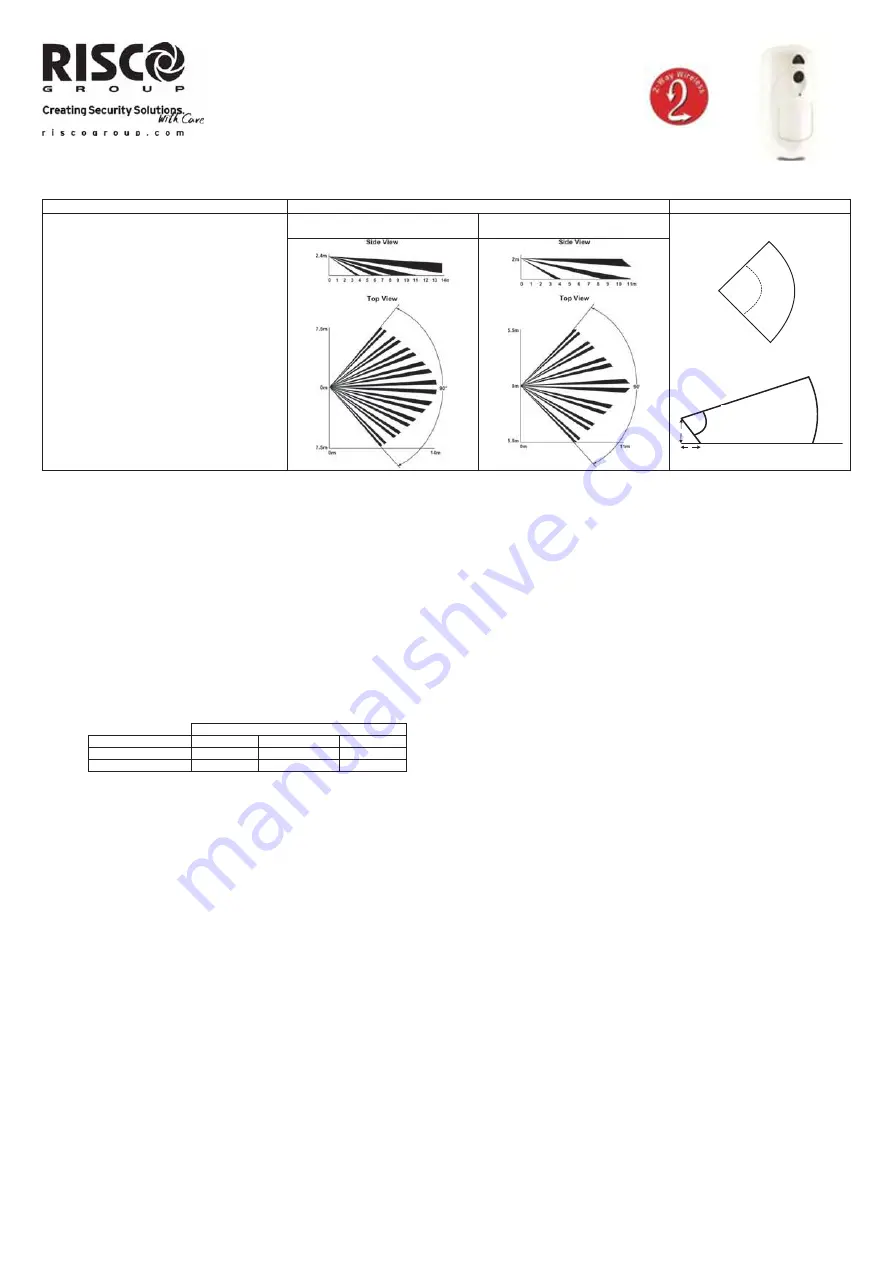
Coverage Patterns
Camera FOV
PIR coverage 12m (40’) wide angle
VGA/VGA camera resolution with ~90° field-of-
view
Discreet IR flash allows imaging in complete
darkness, up to 10m (33’)
Two RF channels with separate antennas:
One for alarms and control; Second channel for
image transmission
Sequence of images upon event, configurable
number and interval and number of images
During disarm, events are ignored to save
battery and for privacy
On-demand images initiated from authorized
mobile phone or web browser
Option for on-arm image taking
Images stored on detector until transmission to
panel is completed
Includes 2 long-life 3V lithium batteries
Works only with video-supporting systems
PIR Model
Pet Friendly Model
Top view
Side view
Installation
Step1: Preliminary Considerations
Select the mounting location for best coverage of the area that is to be protected (see Coverage Patterns).
Pay attention to the following:
Do not touch the lens with your finger as it will result in blurred image capture.
Do not mount the detector in direct sunlight or near heated sources and metal objects.
Detection sectors should be pointed towards either the wall or the floor and not towards windows and curtains.
Select mounting height according to the coverage patterns (recommended: 2.0–2.4 m in height and at least 40cm from ceiling).
Step 2: Registering the Detector into the system
The eyeWAVE must identify itself to the system receiver in a device allocation (enrollment) process, which can be performed by either RF sequence registering or entering the detector’s
11-digit serial number into the system or using RF mode (Panel Quick Key Programming Sequence:
(From the panel) 1) Radio Devices > 1) Allocation > 1) By RF or 2) By Code.
(Through Configuration Software) Click
Radio Device Allocation
> Enter
Serial Code
: [045] + [8 digits];
Indexed
: Automatic or manually designated 1-32;
Accessory Type:
2-Way Detector
(displayed)). Then click
Allocate
: RF Allocation is performed.
Refer to the
Agility Installation
manual for full instructions.
Step 3: Mounting the detector
1. Open the knockout holes of the mounting bracket, and use them as a template for mounting according to the following table (see Figure 1).
Mounting position
Knockout for
Left Flat Right
Bracket
7,8 1,2,3,4 5,6
Tamper 9
10
11
For Pet-Friendly Model:
In order to optimize pet immunity the following guide lines are recommended:
Mount the detector vertically at right angles to the floor.
Make sure an animal cannot get above height of 1.5m (5') by climbing on furniture, shelving or stairs.
2. Fasten the cover to the base of the detector by inserting and fastening screw (B) into the hole located inside the battery compartment. (see Figure 3)
3. Insert the batteries and close the battery compartment cover. (see Figure 3)
4. Once the bracket is installed, slide and lock the detector onto the mounting bracket in reverse sequence. (see Figure 2)
5. Perform a Walk Test as described in the Walk Test section.
6. Insert and fasten screw (C) into the hole located at the bottom of the detector to lock the detector to the mounting bracket. (see Figure 3).
Step 4: Walk Test
Upon inserting the batteries, the detector goes into a Walk Test mode for 20 minutes and then automatically returns to Normal mode (To save battery power). During Walk Test Mode,
the detector will transmit after each detection. Walk test the entire field view of the detector and observe the LED for confirmation. Verify that the receiver is properly receiving the
signals
Manually initiate a walk test from the control panel:
Installation Menu: 2) Testing > 2) Zone > 3) Walk Test 1) Start Walk Test
The detector remains in walk test mode until any key on the panel is pressed. Display test results as follows:
Installation Menu: 2) Testing > 2) Zone > 3) Walk Test 2) Walk Test Results
Camera Configuration
Being bi-directional, the detectors parameters can be modified from the keypad or from the system configuration software according to your needs:
PIR Sensitivity: High/Low (Default: Low)
Supervision Time: 0-255 minutes (Default: 15 min)
LED: On/Off (Default: On)
Operation
Mode.
Walk Test: The detector will transmit after each detection
Normal (Default)
For more information refer to the
Agility Installer Guide.
Configure the c
a
me
ra settings through the RISCO Configuration Software (right-click on the
Serial Code
field in the
Zones
node screen and in the displayed pop-up click
Additional..
) or
through the panel quick key programming sequence as follows (default in
bold
):
Programming > 1) Radio Devices > 1) Allocation > 2) Modification > 1) Zone [Select (1–32)] >
1) Parameters > 6) Advanced 5) Camera Parameters:
1)
Images at Alarm:
3
(1 to 7 images)
2) Image
Interval:
0.5 sec
(0.5, 1, 2 seconds)
3) Pre-Alarm
Image:
Yes
(Yes, No) (Image capture upon each arm)
4) Image
Resolution:
QVGA
(QVGA 320X240, VGA 640X480)
5) Image
Quality:
High
(High, Low)
6) Colour
Image:
Colour
(Colour, B&W)
PIR: D = 2,4 m
PET: D = 2,0 m